Linear motor device

a technology of linear motors and motors, applied in the direction of magnetic circuits characterised by magnetic materials, propulsion systems, magnetic circuit shapes/forms/constructions, etc., can solve the problems of increasing heat loss, increasing temperature, and reducing the power of linear motors, so as to increase the magnetic attraction force, and improve the magnetic shielding effect

Active Publication Date: 2016-10-13
FUJI MASCH MFG CO LTD
View PDF4 Cites 7 Cited by
  • Summary
  • Abstract
  • Description
  • Claims
  • Application Information

AI Technical Summary

Benefits of technology

[0015]According to this, a magnetic shielding target object and a magnetic shielding member are provided on a moving body or path member including the coil, and the magnetic shielding member, which shields the magnetic shielding target object from a magnetic field formed by a magnet, includes a parallel shielding plate and a perpendicular shielding plate. In contrast, conventional technology linear motor devices are either not provided with a magnetic shielding member, or are only provided with a parallel magnetic shielding plate. Thus, according to the present invention, a portion of a magnetic force line, which reaches a magnetic shielding target object when using conventional technology, is effectively shielded by the perpendicular shielding plate and the parallel shielding plate such that it does not reach the magnetic shielding target object, thereby improving the magnetic shielding effect.
[0016]Also, a strong magnetic attraction force

Problems solved by technology

Of particular note are shaft type linear motor devices, which can produce a large thrust with a limited equipment space.
However, with a conventional linear motor

Method used


Image

  • Linear motor device
  • Linear motor device
  • Linear motor device

Examples


Embodiment Construction

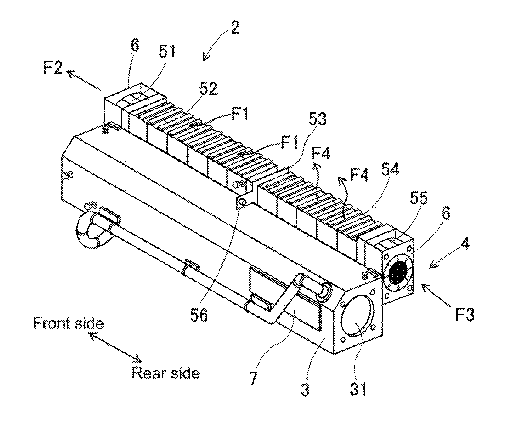
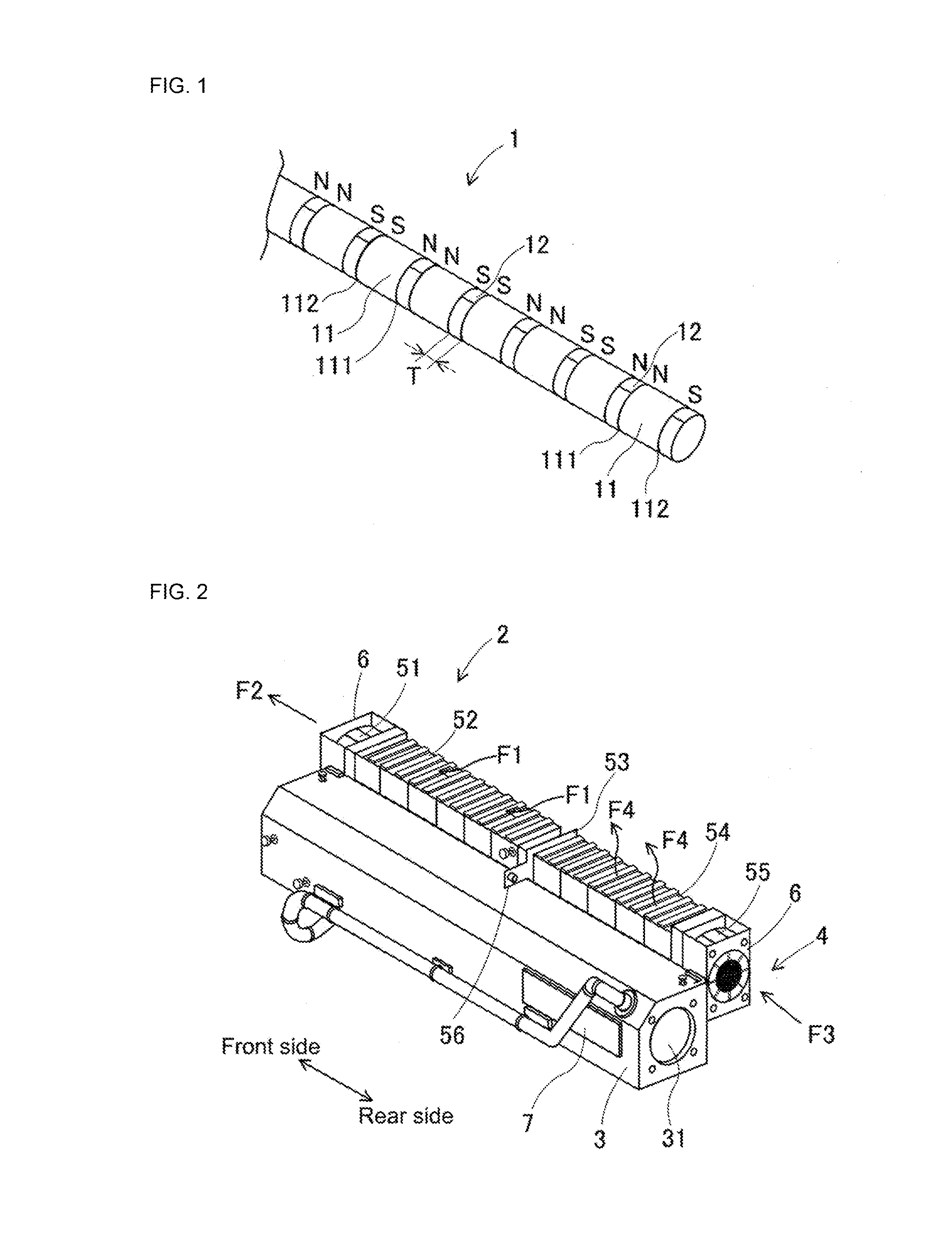
[0032]An embodiment of the linear motor device according to the present invention is described below with reference to FIGS. 1 to 15. The embodiment of the linear motor device is configured from shaft-type path member 1 and tubular moving body 2. FIG. 1 is a perspective view showing the shaft-type path member which configures an embodiment of the linear motor. Shaft-type path member 1 is formed from multiple permanent magnets 11 lined up in a movement direction. FIG. 2 is a perspective view showing tubular moving body 2 which configures an embodiment of the linear motor. Tubular moving body 2 includes inner tube section 31 into which shaft-type path member 1 is inserted, and is movably mounted on shaft-type path member 1. Tubular moving body 2 moves back and forth from the near right side to the far left side of FIG. 2. For convenience, the far left side is referred to as the front side, and the near right side is referred to as the rear side.

[0033]As shown in FIG. 1, shaft-type pat...


PUM


Abstract

A linear motor device comprising: a path member including a magnet extending in a movement direction; and a moving body including a coil that is movably mounted on the path member; the linear motor device generates thrust in the movement direction between the magnet and the coil by current being passed through the coil; the moving body further includes a magnetic shielding target object, and a magnetic shielding member formed from strongly magnetic material that shields the magnetic shielding target. The magnetic shielding member includes a parallel shielding plate provided parallel to the movement direction between the magnetic shielding target object and the magnet, and a perpendicular shielding plate provided extending away from the magnet in a direction perpendicular to the movement direction at at least one of a front edge and a rear edge of the parallel shielding plate in the movement direction.

Description

TECHNICAL FIELD[0001]The present invention relates to a linear motor device with a moving body that moves along a path member by the thrust arising between magnets and a coil through which a current passes, more specifically, it relates to a magnetic shielding structure that mitigates the influence of a magnetic field formed by the magnets.BACKGROUND ART[0002]Equipment such as solder printers, component mounters, reflow ovens, and board inspection machines is used to produce boards mounted with many electronic components. Conventionally, this equipment is connected via board conveyance devices to form a board production line. In component mounters and board inspection machines, ball screw drive devices have been used as drive devices for mounting heads and inspection heads. In recent years, demands have risen for high speed movement and highly accurate positional control of heads, and linear motor devices have come to be used as drive devices. Of particular note are shaft type linea...

Claims


Application Information

Patent Timeline
IPC IPC(8): H02K11/01H02K41/02H02K9/04H02K1/02H02K1/12H02K1/34
CPCH02K11/01H02K1/12H02K41/02H02K9/04H02K1/02H02K1/34H02K41/031H02K9/00H02K11/0141
Inventor NAGATA, RYOKIDO, TAKASHISHIRAKAWA, YOSHIHIROKURONO, MASAKI
Owner FUJI MASCH MFG CO LTD
Why Eureka
Try Eureka