Fixing device and image forming apparatus including same

a technology of fixing device and image forming apparatus, which is applied in the direction of electrographic process apparatus, ohmic resistance heating, instruments, etc., can solve the problems of limited expansion of the surface area difficult to completely withdraw and limited expansion of the electrically conductive member. , to achieve the effect of increasing the magnetic shielding

Active Publication Date: 2012-07-24
KYOCERA DOCUMENT SOLUTIONS INC
View PDF7 Cites 4 Cited by
  • Summary
  • Abstract
  • Description
  • Claims
  • Application Information

AI Technical Summary

Benefits of technology

[0011]It is an object of the present invention to resolve the above-described problems and provide a fixing device that can further increase a magnetic shielding effect and an image forming apparatus having the fixing device installed therein.

Problems solved by technology

However, where the increase in surface area of the electrically conductive member is too large, the electrically conductive member is difficult to withdraw completely from the magnetic field range, and even if the larger portion is withdrawn to the outside of the magnetic field range, the remaining portion still can affect the magnetic field.
Therefore, from the standpoint of increasing the effect of inhibiting an excessive increase in temperature, the expansion of surface area of the electrically conductive member is limited.
When this problem is resolved, it is undesirable to arrange in a row a plurality of individual electrically conductive members that shield a magnetic field.

Method used


Image

  • Fixing device and image forming apparatus including same
  • Fixing device and image forming apparatus including same
  • Fixing device and image forming apparatus including same

Examples


first embodiment

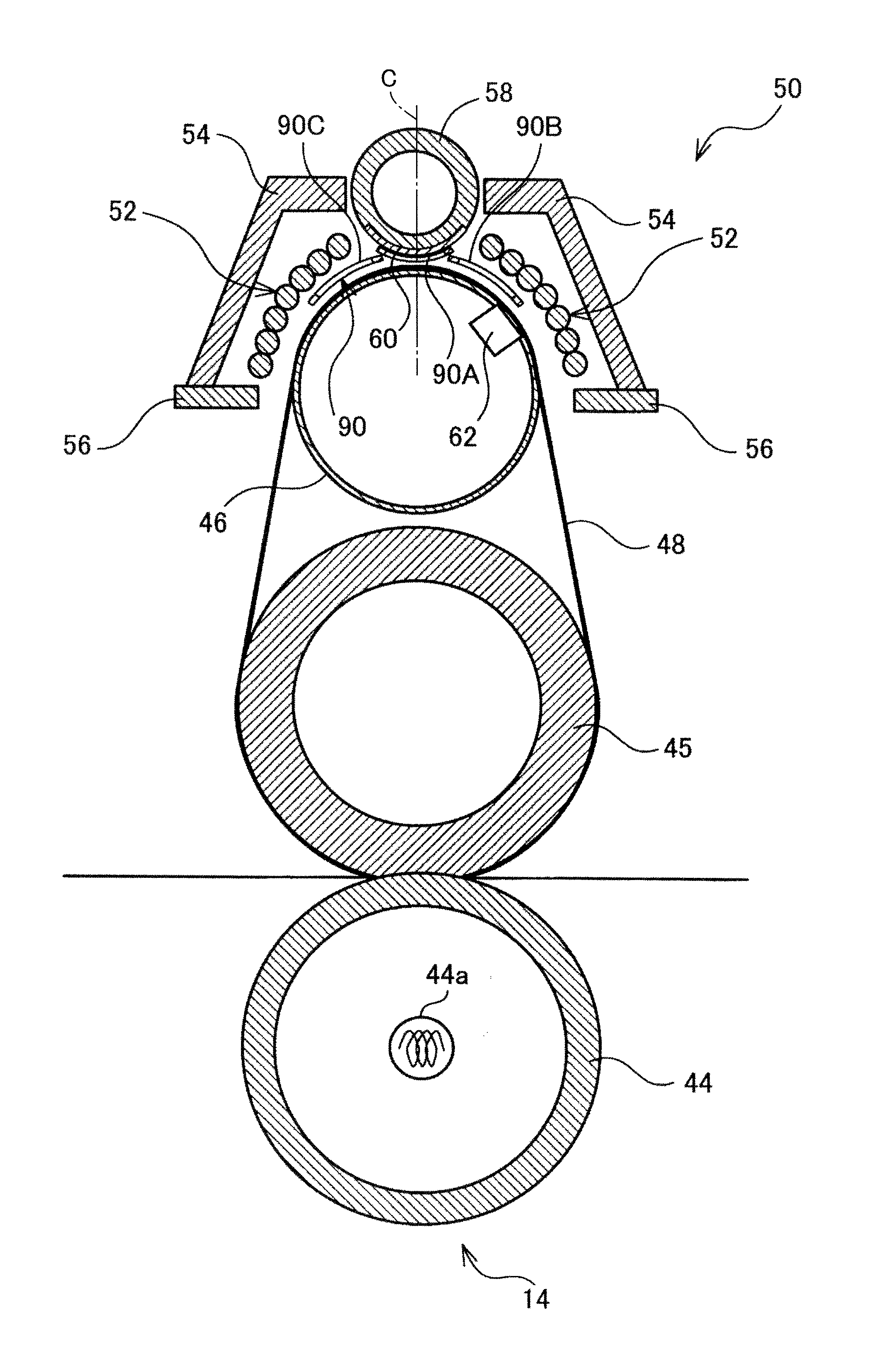
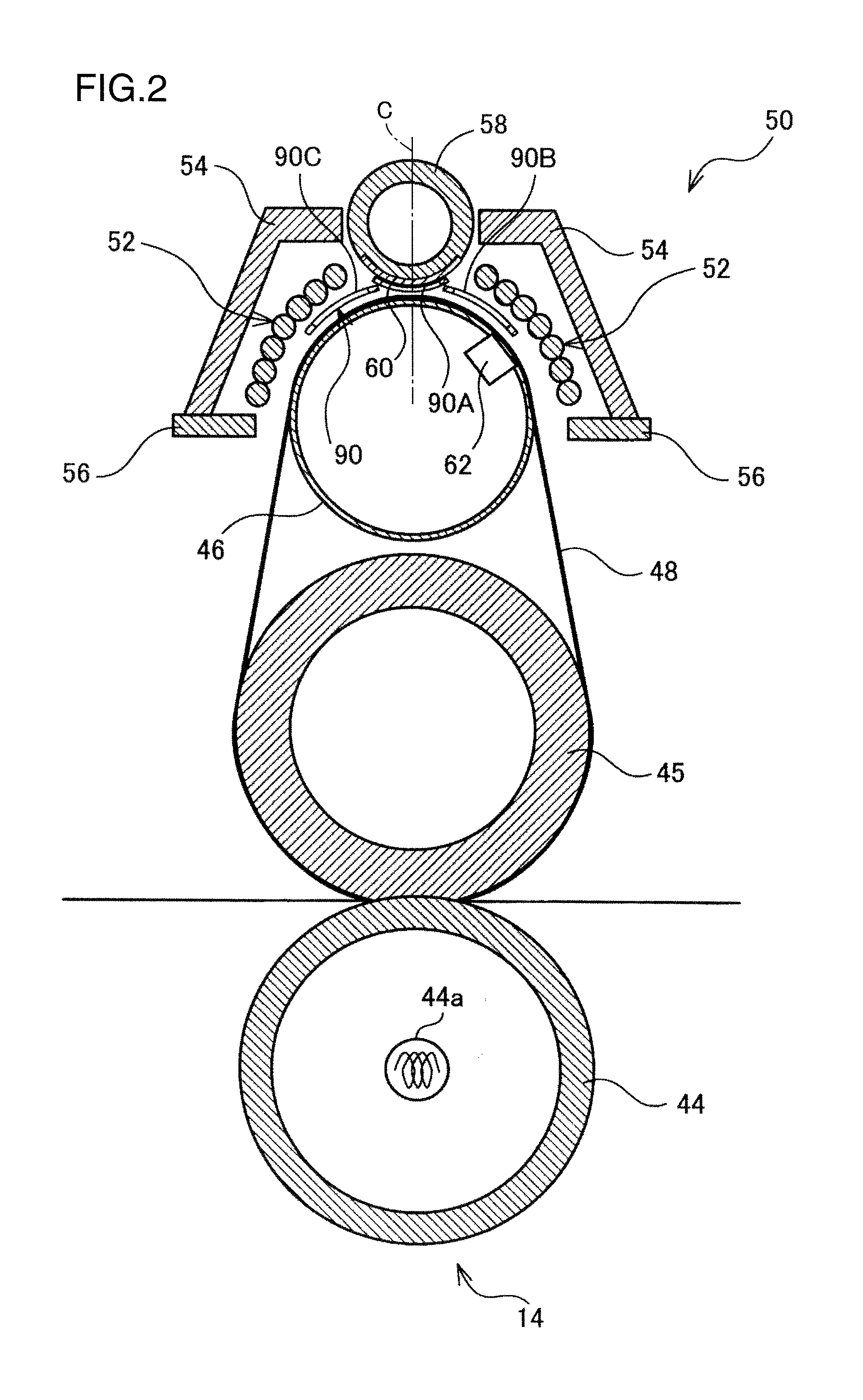
[0055]FIG. 2 is a vertical sectional view illustrating a structural example of the fixing unit 14. FIG. 2 shows a state obtained by rotating the orientation counterclockwise through about 90° from a state in which the fixing unit is mounted on the image forming apparatus 1. Therefore, the sheet conveying direction from below upward, as viewed in FIG. 1, becomes from right to left in FIG. 2. In the case of a larger apparatus main body 2 (all-in-one device), the mounting can be performed with the orientation shown in FIG. 2.

[0056]The fixing unit 14 of the present embodiment is provided with the pressing roller 44 with a diameter of, for example, 50 mm, the fixing roller 45 with a diameter of, for example, 45 mm, the heat roller 46 with a diameter of, for example, 30 mm, and the heating belt 48 with a thickness of, for example, 35 μm (1 μm=1×10⁻⁶ m). The belt 48 is adjusted to a temperature range of, for example, 150 to 200° C. As described hereinabove, the fixing roller 45 has an elas...

second embodiment

[0125]FIG. 10 is a vertical sectional view illustrating a structural example of the fixing unit 14 of the second embodiment. The second embodiment differs from the first embodiment in the arrangement and form of the magnetism adjustment member 90. More specifically, in the magnetism adjustment member 90, the central ring-shaped portion 90A is disposed between the center core 58 and heating belt 48, but the ring-shaped portions 90B, 90C at both sides are disposed outside the inductive heating coil 52, that is, between the arch core 54 and inductive heating coil 52.

[0126]In this example, if the Conditional Equation (1) is satisfied after switching the magnetic path to the first path (a state in which the shielding member 60 is placed in the retracted position), as described hereinabove, the magnetism adjustment member 90 also can cause the magnetic flux to pass effectively in the same manner as in the first embodiment. Further, where the magnetic flux Φ1 passing through the central ri...

third embodiment

[0127]FIG. 11 is a vertical sectional view illustrating a structural example of the fixing unit 14 of the third embodiment. In the third embodiment, a toner image is fixed by the fixing roller 45 and the pressing roller 44, without using the above-described heating belt. In this configuration, for example, a magnetic body similar to the heating belt is wound on the outer circumference of the fixing roller 45, and the magnetic body is inductively heated by the inductive heating coil 52. In this case, the thermistor 62 is provided in a position facing the magnetic body layer on the outside of the fixing roller 45.

[0128]The magnetism adjustment member 90 can be also used as shown in the figure in the fixing unit 14 of the third embodiment.


PUM


Abstract

A fixing device includes a heating member, a pressing member, a coil, a magnetic core, a path switching member switching a magnetic path between a first path and a second path, and a magnetism adjustment member. The magnetism adjustment member allows a passage of a magnetic flux from the magnetic core towards the heating member within the magnetic field range when the magnetic field path is switched to the first path, and shields the magnetic flux without allowing the passage of the magnetic flux within the magnetic field range when the magnetic path is switched to the second path. Further, the magnetism adjustment member has a plurality of ring-shaped portions formed of a single wire material having an endless shape. Each of the ring-shaped portions extends in a longitudinal direction of the magnetic core according to a size of the sheet.

Description

BACKGROUND OF THE INVENTION[0001]1. Field of the Invention[0002]The present invention relates to a fixing device that heats and melts an unfixed toner and fixes the toner to a sheet, while passing the sheet carrying the toner image by nipping between a pair of heated rollers or a heating belt and a roller, and also to an image forming apparatus in which the fixing device is installed.[0003]2. Description of the Related Art[0004]In the image forming apparatuses of the aforementioned kind, a belt system in which a low thermal capacity can be set has recently attracted attention due to a demand for a short warm-up time and reduced energy consumption in the fixing device. An electromagnetic inductive heating system (IH) that enables rapid heating and high-efficiency heating has also attracted attention in recent years, and a large number of products in which the electromagnetic inductive heating is combined with the belt system to reduce energy consumption when fixing color images have ...

Claims


Application Information

Patent Timeline
Patent Type & Authority Patents(United States)
IPC IPC(8): G03G15/20
CPCG03G15/2042G03G2215/2032
Inventor NANJO, YUZURU
Owner KYOCERA DOCUMENT SOLUTIONS INC
Why Eureka
Try Eureka