Apparatus for modelling ocular structures

a technology for ocular structures and apparatuses, applied in the field of ocular models, can solve the problems of inability to provide absolute motion tracking, inability to accurately compensate for motion, and only apply to axial length measurement, etc., to achieve more accurate eye parameter reconstruction and facilitate accurate motion compensation.

Active Publication Date: 2016-10-20
ALCON INC
View PDF2 Cites 7 Cited by
  • Summary
  • Abstract
  • Description
  • Claims
  • Application Information

AI Technical Summary

Benefits of technology

[0023]The provision of instantaneous measurements of the eye position in a plurality of planes facilitates accurate motion compensation as eye roll is taken into account. The combination of the position parameters for eye parameter / ocular modelling provides for more accurate eye parameter reconstruction. For example where the second measuring means is an OCT system providing a time domain A-scan, and the first measuring means is a Purkinje imaging system or other ocular coherence tomography or Scheimpflug imaging system, the apparatus as claimed allows for the whole A-scan to be compensated, and not only the OPD between two surfaces as in a dual beam OLCR implementation. The motion compensated A-scan takes into account lateral eye movement and also axial displacement. The combination of the features allows for a relaxation in scanning. For example if the second measuring means is an OCT system, a slower scanner can be used as it is not essential that the patient stay still as the OCT measurements can be motion compensated.

Problems solved by technology

Some procedures, such as laser vision correction surgery, do not remove or replace existing structures of a patient's eye, or add an implant to the eye, but rather reshape existing structures.
A disadvantage of this system is that motion correction applies only to axial length measurement.
No motion compensation A-scan measurements are possible.
However, this document does not provide for absolute motion tracking.

Method used


Image

  • Apparatus for modelling ocular structures
  • Apparatus for modelling ocular structures
  • Apparatus for modelling ocular structures

Examples


Embodiment Construction

[0065]The aspects of the technology mentioned above, as well as additional aspects, will now be described in greater detail. The aspects may be used individually, all together or in any combination of two or more, as the technology is not limited in this respect.

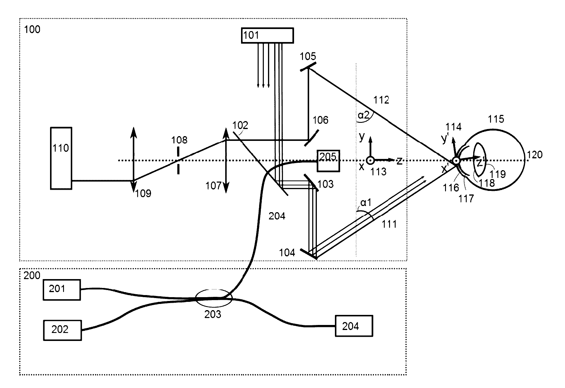
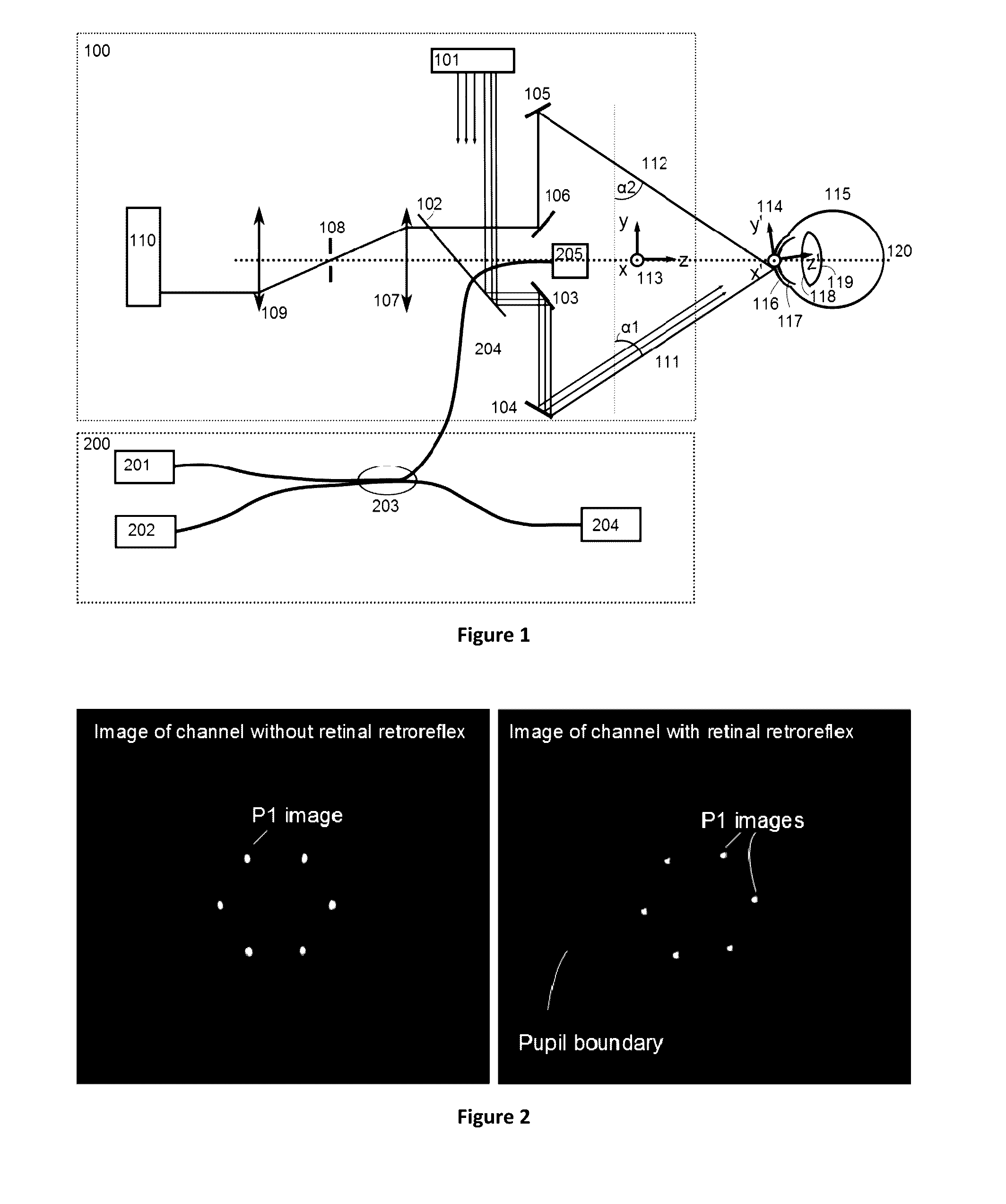
[0066]The system shown in FIG. 1 illustrates a configuration of an optical system combining a Purkinje Mirror Imaging (PMI) Modality 100 and an Optical Low Coherence Reflectometry (OCLR) 200 for ocular measurements of structures of interest in accordance with the present invention. A structure of interest may be a complete structure (e.g., a lens) or a surface (e.g. the front of the lens) and a parameter may be the shape, thickness or refractive index of the structure of interest. Any of these parameters may be of interest either as an ultimate result or a means for determining other parameters or for both purposes. For example, the shape of the cornea may be of interest as an end result for modelling the cornea, but may als...


PUM


Abstract

An apparatus for motion compensated modelling of a parameter of an eye, comprising: a first measuring means for measuring a plurality of position parameters of the eye with respect to an optical reference coordinate system of the apparatus; a second measuring means for measuring an interference signal at a plurality of optical reference coordinates, wherein the measurement of the plurality of position parameters and measurement of the interference signal are time synchronised; means for correcting the interference signal to account for a displacements of a parameter of the plurality of position parameters; and means for modelling the eye parameter based at least in part on the corrected interference signal.

Description

TECHNICAL FIELD[0001]The technology described herein relates to ocular modelling and in particular motion compensated modelling of a parameter of an eye.BACKGROUND ART[0002]Ocular procedures often modify one or more structures of the eye, such as the cornea, lens or retina. Some procedures involve removing or replacing one or more structures of the eye, or adding an implant. For example, lens replacement surgery involves removing a patient's existing lens and replacing it with a new lens. Some procedures, such as laser vision correction surgery, do not remove or replace existing structures of a patient's eye, or add an implant to the eye, but rather reshape existing structures. Regardless of the type of modification being made (e.g. removal, replacement, insertion, or alteration), the optical performance of the eye is altered by adjustments made to the structures of the eye. Therefore in order to accurately model the structure of any eye, it is necessary to determine the ocular para...

Claims


Application Information

Patent Timeline
Patent Type & Authority Applications(United States)
IPC IPC(8): A61B3/00A61B3/113A61B3/103G01B9/02A61B3/10
CPCA61B3/0025G01B9/02091A61B3/113A61B3/103A61B3/102
Inventor BOSS, DANIELMROCHEN, MICHAELNOLAN, ANDREWZAKHAROV, PAV
Owner ALCON INC
Why Eureka
Try Eureka