
Operation section and liquid ejection device

a liquid ejection device and operation section technology, applied in the direction of fluid jet surgical cutters, application, vaccination/ovulation diagnostics, etc., can solve problems such as difficulty in accurate operation, and achieve the effect of excellent operability

Inactive Publication Date: 2016-10-20
SEIKO EPSON CORP
View PDF3 Cites 1 Cited by
  • Summary
  • Abstract
  • Description
  • Claims
  • Application Information

AI Technical Summary

Benefits of technology

The liquid ejection device described in this patent allows for accurate medical practice with excellent operability. The device includes a gripper section with an adjustable suction force, allowing for easy adjustment with the thumb while maintaining a stable posture. The device can also suck in liquid containing fragmentated tissue at the desired force for medical practice. Overall, this device provides a high level of operability for medical professionals.

Problems solved by technology

Therefore, in the operation of the operation section, the tube group connected to the operation section bends and twists and therefore produces reaction force, so that the posture of the operation section tends to be unstable, resulting in a difficulty in accurate operation.

Method used


Image

  • Operation section and liquid ejection device
  • Operation section and liquid ejection device
  • Operation section and liquid ejection device

Examples


first embodiment

Variations of First Embodiment

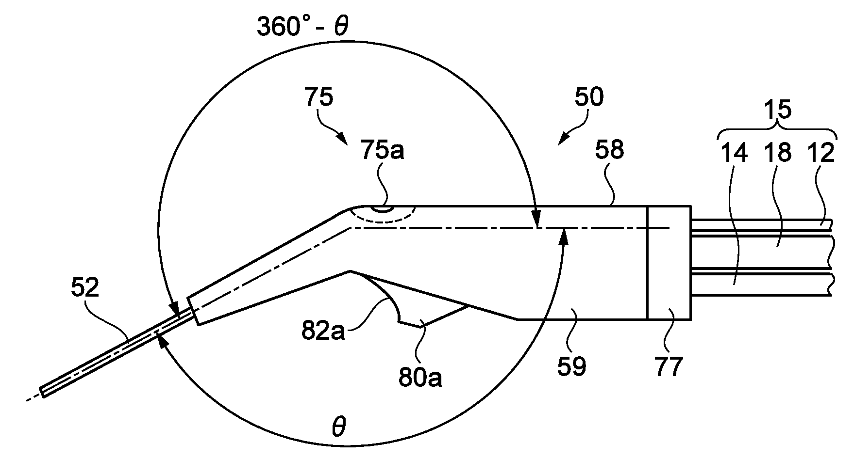
[0074]A variety of changes can be made to the first embodiment described above to the extent that the changes do not depart from the substance of the invention. For example, variations different from the embodiment described above will be described with reference to FIGS. 5A to 5C. FIGS. 5A to 5C show variations of the first embodiment.

[0075]The embodiment described above has been described with reference to the case where the finger position fixing section 80a is formed as a single arcuate recess, but the finger position fixing section is not necessarily configured this way. The finger position fixing section may be a finger position fixing section 80b shown in FIG. 5A, which has, in addition to the arcuate recess positioned in the direction toward the nozzle section 52, a finger rest section 82b, which is formed along a lower portion of the main body case 59 and formed of a plurality of arcuate recesses on which the other fingers rest. The operation s...

second embodiment

[0078]A finger position fixing section according to a second embodiment will be described with reference to FIGS. 6A and 6B. FIGS. 6A and 6B describe the finger position fixing section according to the second embodiment. FIG. 6A is an exterior perspective view of the finger position fixing section, and FIG. 6B shows an aspect in which the finger position fixing section is attached to the operation section. The same configurations and contents as those in the first embodiment have the same reference characters and will not be described.

[0079]A finger position fixing section 80e according to the second embodiment is a part independent of the main body case 59 of the operation section 50. The finger position fixing section 80e is preferably formed, for example, in metal sheet processing and has a finger rest section 82e and an attachment section 85e, as shown in FIG. 6A. The attachment section 85e is formed of a metal sheet so bent and shaped as to follow the bottom surface of the main...


PUM


Abstract

An operation section used to form a liquid ejection device that ejects liquid includes a tubular nozzle section through which the liquid is ejected, and a gripper section in which the nozzle section is so disposed as to protrude through one side of the gripper section and a tube group including a tube through which the liquid flows and a cable through which a drive signal is supplied is connected to another side of the gripper section, and the gripper section is provided with a finger position fixing section on which any of an operator's fingers rests when the operator grips the gripper section.

Description

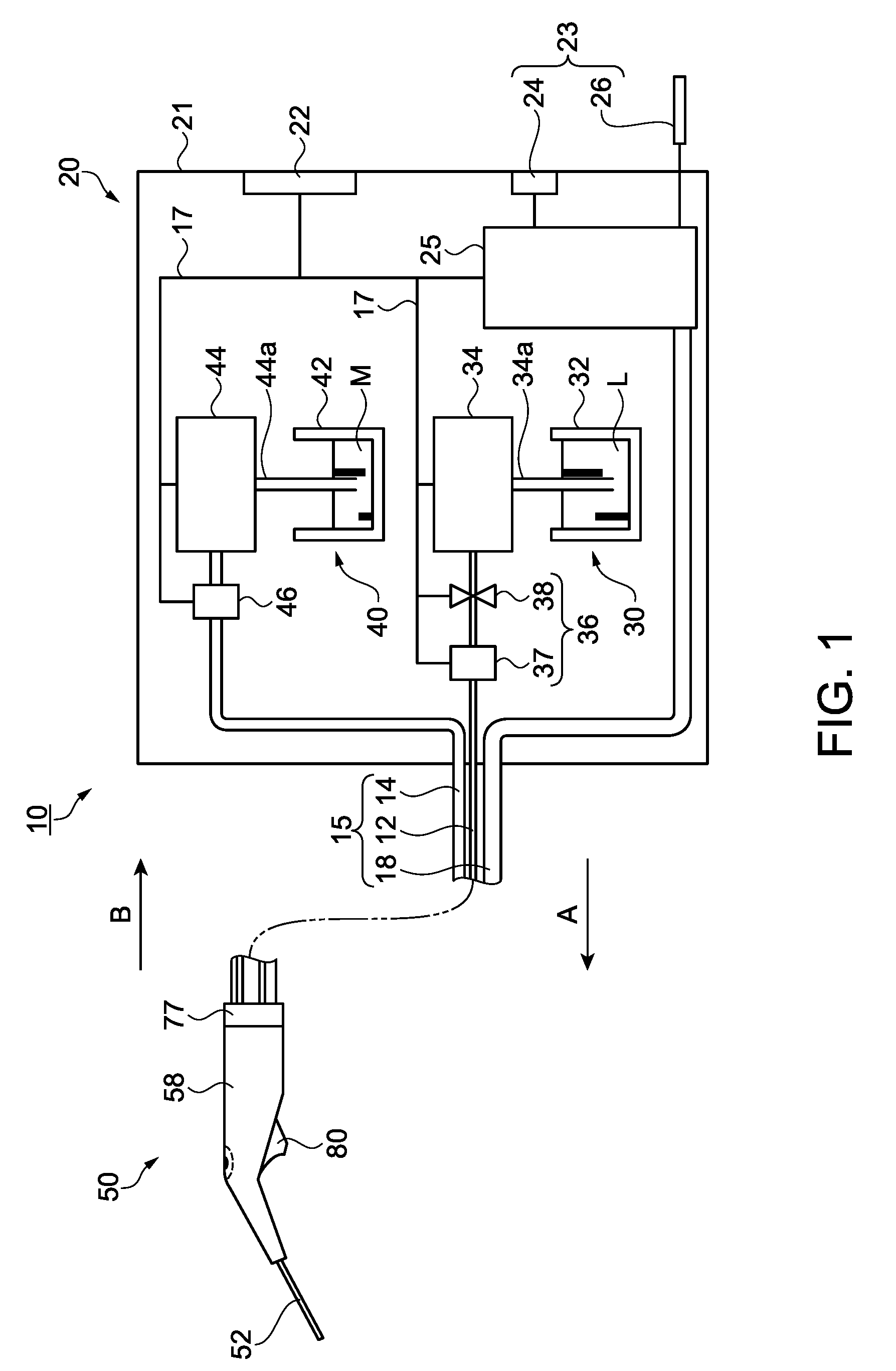
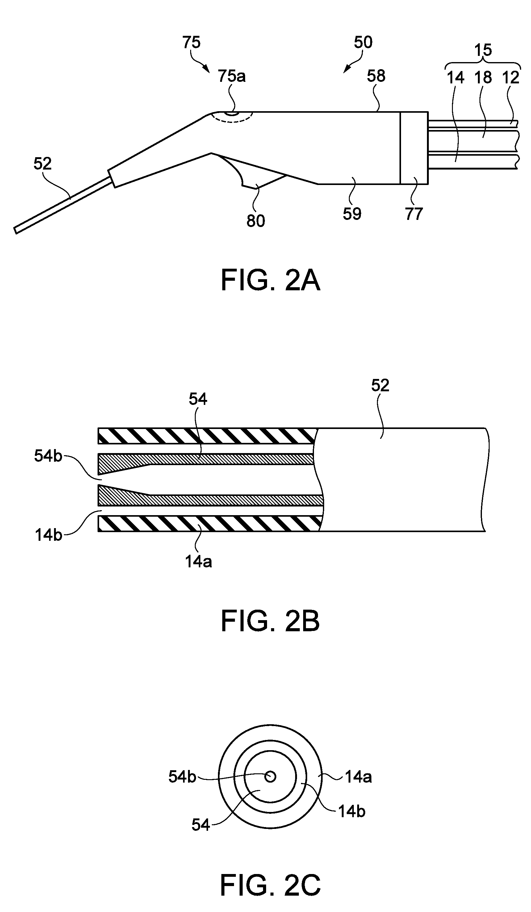
BACKGROUND[0001]1. Technical Field[0002]The present invention relates to an operation section having a nozzle section through which liquid is ejected and a liquid ejection device including the operation section.[0003]2. Related Art[0004]In recent years, in a medical field, such as an incision and removal of living tissue, a liquid ejection device is used because many advantages, such as an ability to maintain the surface of living tissue at a surgical operation site at a low temperature and no injury of blood vessels and bodily parts, attract attention. A liquid ejection device ejects liquid, such as physiological saline, in the form of pulsed flow toward a living body to excise or fragmentate living tissue. A practitioner grips a handpiece (hereinafter referred to as an operation section) including a nozzle through which the liquid is ejected for medical practice (see JP-A-9-224951, for example).[0005]As medical treatment advances, a variety of kinds of biological sites become targ...

Claims


Application Information

Patent Timeline
IPC IPC(8): B41J2/165
CPCB41J2/1652A61B10/0283A61B17/3203A61B2017/00154A61B2217/005A61M1/7411A61B18/00A61B2218/002
Inventor IDE, KATSUYA
Owner SEIKO EPSON CORP
Learn More