Spool valve, in particular for an automatic transmission of a motor vehicle

a technology for automatic transmission and valve body, which is applied in the direction of valve housing, valve operating means/releasing devices, mechanical equipment, etc., to achieve the effects of reducing costs, large hydraulic cross-section, and simplifying the manufacture of the valve spool and also the spool sleev

Active Publication Date: 2016-10-20
ROBERT BOSCH GMBH
View PDF6 Cites 4 Cited by
  • Summary
  • Abstract
  • Description
  • Claims
  • Application Information

AI Technical Summary

Benefits of technology

[0009]In another embodiment of the spool valve, the valve spool has an essentially identical diameter in a respective area of the first and second control section on the spool side, and is therefore configured essentially with a non-incremental diameter. In this way, the manufacture of the valve spool and also the spool sleeve may be simplified and at reduced costs.
[0010]It may further be provided that the connection channel includes at least two axially extending sub-channels, which are situated at a radial angle of 90 degrees relative to at least one of the radial connections of the spool valve. The sub-channels are formed with the aid of recesses and / or cavities in the section made of plastic. This allows for a comparatively large hydraulic cross-section of the connection channel, and thereby improves the operation of the spool valve. For example, at least sections of the axial sub-channels have an approximately circular segment-shaped or crescent-shaped cross section. This results in a cross sectional shape for the connection channel extending axially in sections, which is particularly suited for the spool valve according to the present invention.

Problems solved by technology

An external hydraulic connection to the working connection and an additionally required hydraulic connection on the housing of the spool valve, are in particular, unnecessary.

Method used


Image

  • Spool valve, in particular for an automatic transmission of a motor vehicle
  • Spool valve, in particular for an automatic transmission of a motor vehicle
  • Spool valve, in particular for an automatic transmission of a motor vehicle

Examples


Embodiment Construction

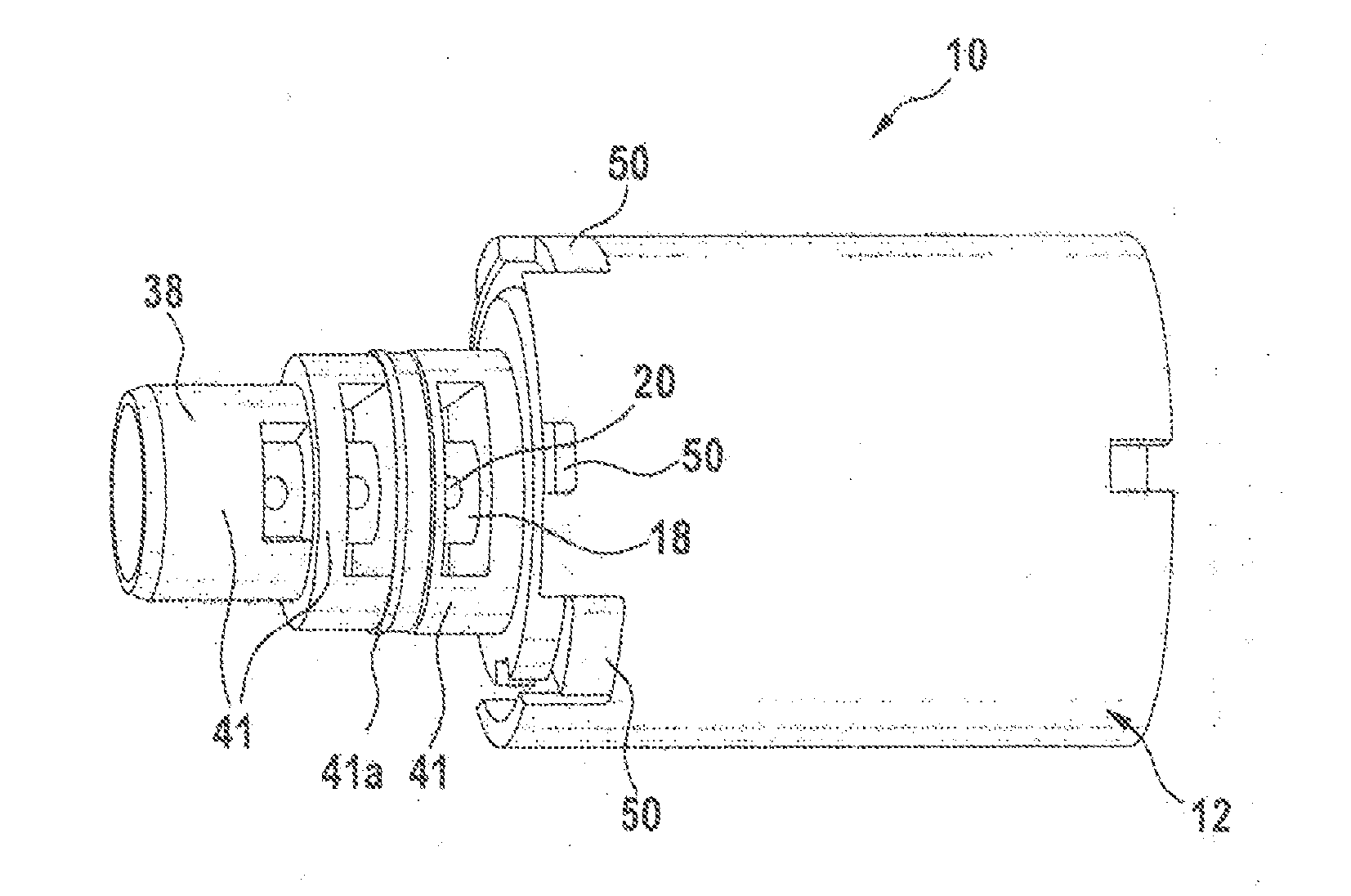
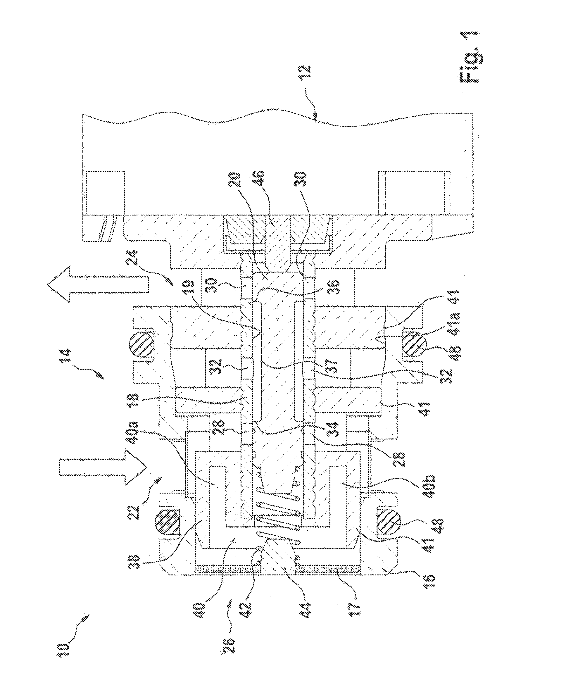
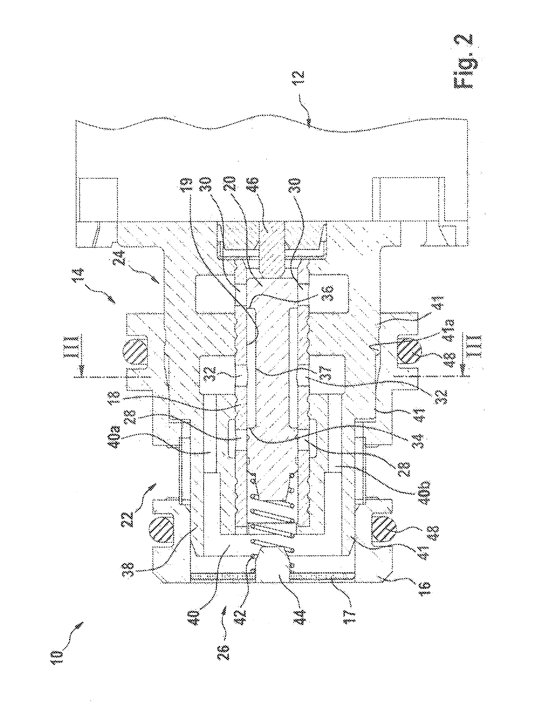
[0019]FIG. 1 shows an axial sectional view of a spool valve 10 for an automatic transmission (not shown) of a motor vehicle. An electromagnetic actuator 12 actuating spool valve 10 is depicted in a partial exterior view in an area to the right in FIG. 1.

[0020]Spool valve 10 includes a housing 14 having an approximately hat-shape configured, radially outer shell element 16, which is a plastic injection molded part. A filter screen 17 is situated on the front face (i.e., to the left in FIG. 1) of the outer shell element 16. Filter screen 17 is injection-molded into shell element 16. Housing 14 also includes an essentially cylindrically formed spool sleeve 18, on which a guide recess 19 is formed radially inside extending approximately over the entire axial length of spool sleeve 18. A valve spool 20 is axially movable and guided essentially fluid-tight in guide recess 19.

[0021]Housing 14 also includes a radial inlet connection 22 and a radial outlet connection 24 spaced axially apart ...


PUM


Abstract

A spool valve, for a motor vehicle's automatic transmission, having a housing and an axially movable valve spool in a guide recess of the housing, including at least one radial inlet connection and one radial outlet connection spaced axially apart therefrom, and a working connection on the front face, at least one first control opening connected to the inlet connection and one second control opening spaced axially apart therefrom and connected to the outlet, and one third control opening situated axially between these two and connected to the working connection being present on the guide recess, the control openings being hydraulically cooperate-able with one first and second control section on the valve spool, and a connection channel extending axially in sections being in the housing, connecting the third control opening to the working connection.
The housing includes a section made of plastic, in which the connection channel is formed.
SUBSTITUTE SPECIFICATION 12

Description

FIELD OF THE INVENTION[0001]The present invention relates to a spool valve.BACKGROUND INFORMATION[0002]Automatic transmissions for motor vehicles are believed to be available, which use hydraulically actuatable clutches for changing gears. A comparatively high precision of the hydraulic components is required in order for gear shifts to proceed smoothly and unnoticeable to the driver. Electromagnetically actuatable pressure control valves, for example, are used for such purposes. Patent publications from this technical field include, for example, DE 198 47 021 B4 and DE 201 00 950 U1.SUMMARY OF THE INVENTION[0003]The problem underlying the present invention may be solved by a spool valve as described herein. Advantageous refinements are specified in the further descriptions herein. Features important for the present invention are also found in the following description and in the drawings, whereby the features may be important to the present invention, both alone and in different co...

Claims


Application Information

Patent Timeline
Patent Type & Authority Applications(United States)
IPC IPC(8): F16K27/04F16K31/06F16H61/02F16K11/07
CPCF16K27/041F16K11/07F16H2061/0253F16H61/0251F16K31/0613
Inventor ESZTERLE, MARCELSCHUDT, KLAUS
Owner ROBERT BOSCH GMBH
Why Eureka
Try Eureka