
Automatic Firearm Magazine Loader

a technology of automatic firearms and loaders, which is applied in the field of firearms, can solve the problems of time-consuming and stressful loading process of users, pain for users, and difficulty in loading firearm magazines by hand, and achieves the effects of reducing the cost of operation, and improving the service li

Inactive Publication Date: 2016-10-20
MOKUOLU RICHARD
View PDF14 Cites 22 Cited by
  • Summary
  • Abstract
  • Description
  • Claims
  • Application Information

AI Technical Summary

Benefits of technology

The invention described in this patent can have various benefits. The technical effects of the invention may not be fully described in this summary.

Problems solved by technology

Firearm magazines are difficult and oftentimes ergonomically challenging to load by hand.
This is time consuming, can be painful for the user, and requires the user to remove gloves in cold weather.
Further, current loaders require user input which can lead to injury.
This loading process is time consuming and stressful for the user.
This loading process is also time consuming and can fatigue the user.

Method used


Image

  • Automatic Firearm Magazine Loader
  • Automatic Firearm Magazine Loader
  • Automatic Firearm Magazine Loader

Examples


first embodiment

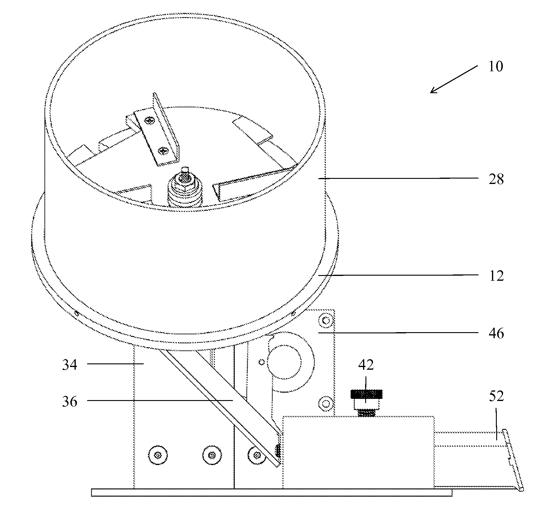
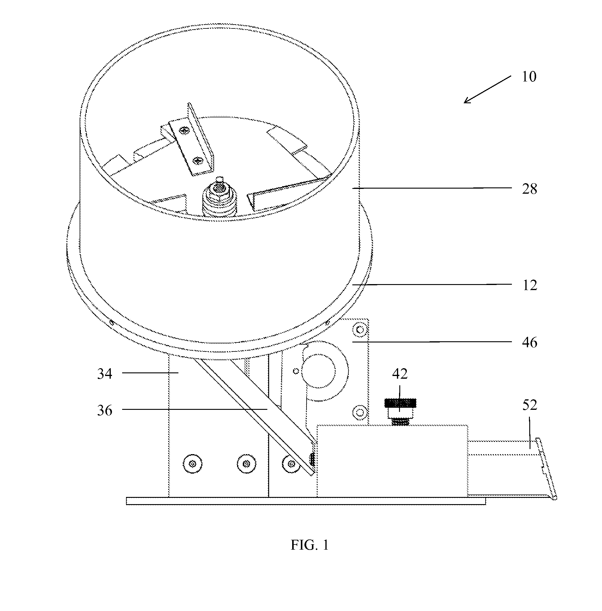
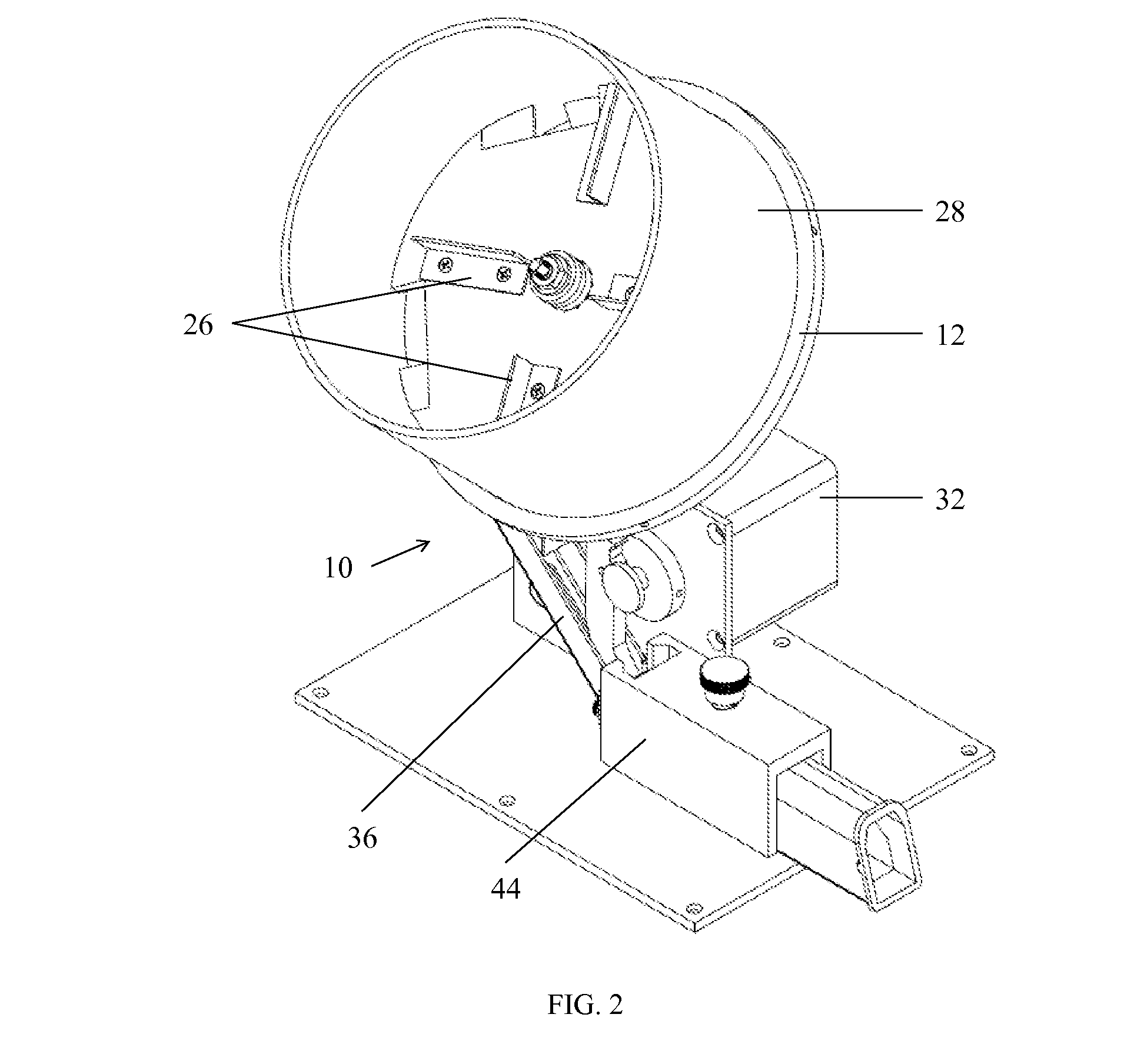
[0025]the present invention is shown in detail in FIG. 1, FIG. 2, FIG. 3, FIG. 4, and FIG. 5. Disclosed is an automatic firearm magazine loading device 10 shown with an elevated hopper system placed at a 45 degree angle, and a motor loading system. The hopper system comprises of a hopper base 12, stationary hopper ring 14, hopper ramp 16, optical sensor 18, hopper rotor base 20, hopper hub 22, hopper disc 24, hopper agitator 26, hopper wall 28, bullet stop 30, a servo motor 32, hopper mount 34, and hopper chute 36. The motor loading system comprises of a servo motor 32, rotating arm 38, motor drive gear 40, thumb screw 42, magazine slide 44, and motor mount 46. Both the hopper system and motor loading system are built on a base 48.

[0026]In more detail, still referring to the invention of FIG. 1, FIG. 2, FIG. 3, FIG. 4, and FIG. 5, the motor loading system compresses the spring of the firearm magazine 46 for loading using a servo motor 32, motor drive gear 40, and rotating arm 38. Th...

second embodiment

[0027]the present invention is shown in detail in FIG. 6, FIG. 7, FIG. 8, FIG. 9, FIG. 10, and FIG. 11. Disclosed is an automatic firearm magazine loading device 10 with an elevated hopper system placed at a 45 degree angle, and an actuator loading system. The hopper system comprises of a hopper base 12, stationary hopper ring 14, hopper ramp 16, optical sensor 18, hopper rotor base 20, hopper hub 22, hopper disc 24, hopper agitator 26, hopper wall 28, a servo motor 32, hopper lid 54, hopper basket 56, hopper stand 58, and loading chute 60. The actuator loading system comprises of a loading channel 62, micro actuator connector 64, loading arm 66, micro linear actuator 68, magazine housing 70, loading insert 72, actuator connector 74, linear actuator 76, toggle clamp 78, clamp base 80, and adjustable backing plate 82. Both the hopper system and actuator loading system are built on a base 48.

[0028]In more detail, still referring to the invention of FIG. 6, FIG. 7, FIG. 8, FIG. 9, FIG....


PUM


Abstract

The present invention is an automatic firearm magazine loader that has an elevated hopper system, a loading system, and a mechanism for compressing a firearm magazine comprising a spring mechanism. The firearm magazine is compressible upon compression of the spring mechanism. The loading system facilitates the loading of a firearm ammunition into the firearm magazine upon the compression of the firearm magazine, and the compression of the firearm magazine is motor driven. The device is an automatic firearm magazine loader for a designated number of rounds of ammunition. The design consists of a user interface used to select the preferred number of rounds of ammunition to load, a hopper system which feeds individual rounds of ammunition in a set orientation, and a loading system which loads the individual rounds of ammunition into a firearm magazine.

Description

CROSS-REFERENCE TO RELATED APPLICATIONS[0001]Not Applicable.STATEMENT REGARDING FEDERALLY SPONSORED RESEARCH OR DEVELOPMENT[0002]Not ApplicableREFERENCE TO SEQUENCE LISTING, A TABLE, OR A COMPUTER PROGRAM LISTING COMPACT DISK APPENDIX[0003]Not ApplicableBACKGROUND OF THE INVENTION[0004]1. Field of the Invention[0005]The present invention relates to the field of firearms. More particularly, the present invention relates to a method and device for facilitating the loading of firearm ammunition into a firearm magazine.[0006]2. Description of the Related Art[0007]Firearm magazines are difficult and oftentimes ergonomically challenging to load by hand. This is time consuming, can be painful for the user, and requires the user to remove gloves in cold weather. The difficulties of loading firearm magazines even with the use of a hand loader are multiplied for users with certain conditions. Further, current loaders require user input which can lead to injury.[0008]Current firearm magazine l...

Claims


Application Information

Patent Timeline
Patent Type & Authority Applications(United States)
IPC IPC(8): F41A9/83
CPCF41A9/83F41A9/24
Inventor MOKUOLU, RICHARD
Owner MOKUOLU RICHARD
Learn More