Dynamic transaction card power management

a transaction card and power management technology, applied in the field of printed circuit boards, can solve the problems of long charge time, large space occupation of batteries in smaller electronic devices, and provide relatively slow power delivery, and achieve the effects of rapid energy storage, rapid energy storage, and high energy density

Active Publication Date: 2016-10-20
CAPITAL ONE SERVICES
View PDF18 Cites 25 Cited by
  • Summary
  • Abstract
  • Description
  • Claims
  • Application Information

AI Technical Summary

Benefits of technology

[0014]In an example embodiment, the power source may include an ultracapacitor, which may provide higher energy density fast discharge / charge time, low level of heating, safety, long-term operation stability and no disposable parts. For example, by utilizing an ultracapacitor, a dynamic transaction card may be charged via insertion into EMV terminals for payment, without requiring extra activities from the customer.
[0016]As referred to herein, an ultracapacitor may be understood to be readily integrated onto a PCB. An ultracapacitor may be configured to include, two electrodes, which may include porous plates submerged in an electrolyte solution and separated by a thin insulator. The distance between the two charged layers may be measured in nanometers. The porosity of the plates may greatly increase the surface area available for holding charge. A diode in series with an ultracapacitor may be utilized so that the capacitor holds charge by only allowing current flow in one direction.
[0018]In an example embodiment, a part of the PCB may be used as a part of the capacitor itself so that the capacitor may be printed on the PCB. This may allow for PCB height savings of approximately 7 to 8 mils.
[0027]Various embodiments of the present disclosure utilize a printed circuit board (“PCB”) with a rapid energy storage device. As an example, an rapid energy storage device, which may provide higher energy density fast discharge / charge time compared to lithium-polymer batteries, low level of heating, safety, long-term operation stability and no disposable parts. For example, by utilizing a rapid energy storage device, a dynamic transaction card may be charged via insertion into EMV terminals for payment, without requiring extra activities from the customer.

Problems solved by technology

The power source utilized to power smaller electronics may dictate the size and shape of the devices, and may often result in long charge times and / or provide relatively slow power delivery.
However, batteries often consume a large percentage of space in smaller electronic devices, which poses design limitations where a device must be a particular size or shape for user or compatibility purposes (e.g., to fit in the palm of a user's hand, to be compatible with a machine that receives the device, etc.).
This current design also requires the use of complicated smart card power management topology.

Method used


Image

  • Dynamic transaction card power management
  • Dynamic transaction card power management
  • Dynamic transaction card power management

Examples


Embodiment Construction

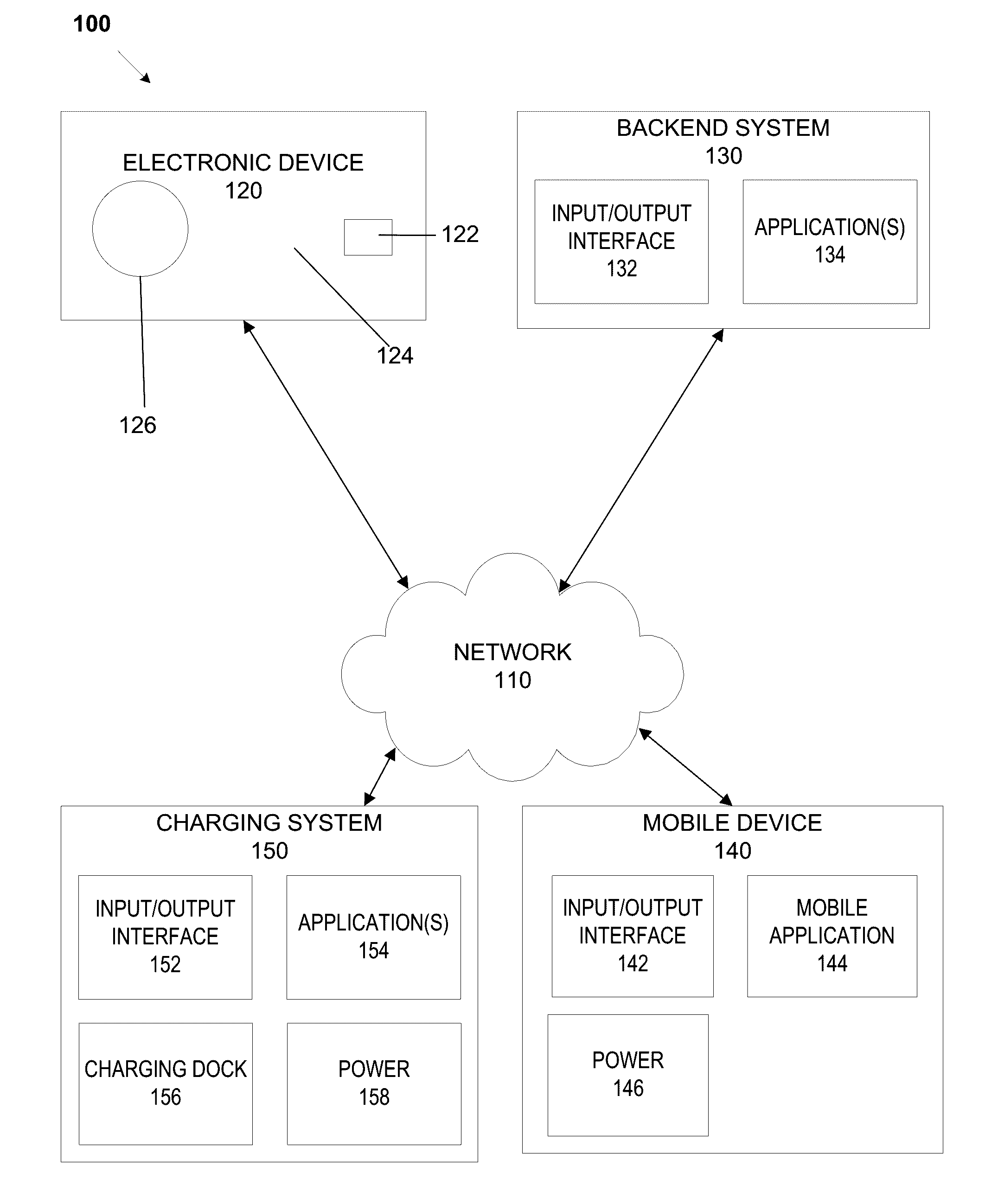
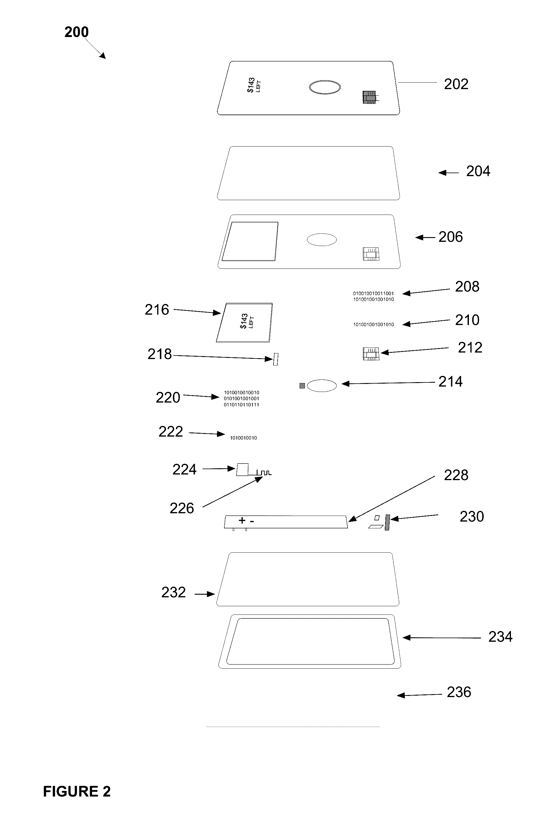
[0037]The following description is intended to convey a thorough understanding of the embodiments described by providing a number of specific example embodiments and details involving a PCB with a power source and methods for manufacturing a PCB with a power source, to enable a dynamic transaction card to draw the power it needs to communicate with a smartphone via insertion into EMV terminals for payment. The associated system may harvest energy from an EMV terminal to charge or recharge a dynamic transaction card when the card is inserted into a terminal. It should be appreciated, however, that the present disclosure is not limited to these specific embodiments and details, which are examples only. It is further understood that one possessing ordinary skill in the art, in light of known systems and methods, would appreciate the use of the invention for its intended purposes and benefits in any number of alternative embodiments, depending on specific design and other needs. A dynam...


PUM


Abstract

A printed circuit board (“PCB”) with a power source. The PCB and power source combination may be inserted into a small electronic device, such as a dynamic transaction card, which may include a dynamic transaction card or a EuroPay-MasterCard-Visa (“EMV”) card. For example, a PCB may be manufactured to attach a battery as a power source to one side of a PCB such that the integrated battery directly connects with at least a portion of the PCB side. A rapid energy storage device may also be utilized as a power source. Energy may be harvested from an EMV terminal to charge or recharge a dynamic transaction card or EMV card powered by a rapid energy storage device when the card is inserted into the terminal.

Description

CROSS REFERENCE TO RELATED APPLICATIONS[0001]This application claims the benefit of U.S. Provisional Application No. 62 / 266,324 entitled “Printed Circuit Board with Integrated Battery” filed Dec. 11, 2015, U.S. Provisional Application No. 62 / 270,307 entitled “Capacitive Powertrain for a Smart Card” filed Dec. 21, 2015, and U.S. Provisional Application No. 62 / 305,599 entitled “Smart Card Europay MasterCard Visa (“EMV”) Terminal Energy Harvesting” filed Mar. 9, 2016; and U.S. Provisional Application No. 62 / 147,568 entitled “System Method, and Apparatus for a Dynamic Transaction Card” filed Apr. 14, 2015. The entire contents of these applications are incorporated herein by reference.[0002]This application is related to U.S. application Ser. No. 14 / 338,423, entitled “System and Method for Exchanging Data with Smart Cards” filed Jul. 23, 2014, which claims the benefit of U.S. Provisional Application No. 61 / 857,443 filed Jul. 23, 2013. The entire contents of these applications are incorpo...

Claims


Application Information

Patent Timeline
Patent Type & Authority Applications(United States)
IPC IPC(8): H02J4/00G06K19/07H02J7/02
CPCH02J4/00G06K19/0701H02J7/025G06K19/0704G06K19/07707H02J7/345H02J50/001H02J50/00
Inventor LOCKE, TYLERWURMFELD, DAVIDZARAKAS, JAMESKOEPPEL, ADAM
Owner CAPITAL ONE SERVICES
Why Eureka
Try Eureka