Eureka AIR delivers breakthrough ideas for toughest innovation challenges, trusted by R&D personnel around the world.

Compact power transfer mechanism using induced emf

Active Publication Date: 2016-10-20
HANCHETT ENTRY SYST
View PDF9 Cites 3 Cited by
  • Summary
  • Abstract
  • Description
  • Claims
  • Application Information

AI Technical Summary

Benefits of technology

The present invention is a power-transfer system that allows for the transfer of resonant inductive power from one object to another. The system includes a transformer portion with a core and circuitry for transferring the electromagnetic field to the receiver portion on the second object. A timer / sensor is included to monitor the position of the second object and can trigger power transfer to a limit set by a timing circuit. The first circuitry controls the voltage output from a power source, while the second circuitry converts the induced AC voltage to DC voltage. The system can be used in various applications such as door frames and doors.

Problems solved by technology

Resonant inductive coupling having one portion mounted in the door and a corresponding mating portion mounted in the door frame provides a viable solution to the industry's long-felt need but also poses challenges for those with skill in the art, such as ensuring the electromagnetic field properly transfers across the distance of the gap between the door and its corresponding door frame (or, in certain instances, a mullion), regardless of the gap's unique characteristics, and the need for the installed components to occupy a minimal amount of space such as no more than a one inch diameter space in the door and a one inch diameter space in the door frame.
Another challenge posed to the skilled artisan, particularly when using solenoid actuators, is that no less than six watts of power must be transferred from the door frame to the door for a duration of time that is long enough to move the actuator (load), which in turn ultimately releases the locking mechanism.
The problem with this wire-based approach is that only fine wires with very small diameters can be used, since such wires must pass internally through the plates of the door hinges to avoid being severed during normal operation or by an unwanted intruder.
The spring-loaded contacts approach presents a different set of problems relating to contamination of the contacts and the risk of electrical shock if the user comes into physical contact with the electrically active contact portion installed on the frame.
However, these systems require at least the transmitter component or the receiver component to extend outwardly and beyond the plane of the door or door frame where it will be exposed and prone to damage or become disabled.

Method used


Image

  • Compact power transfer mechanism using induced emf
  • Compact power transfer mechanism using induced emf
  • Compact power transfer mechanism using induced emf

Examples


Embodiment Construction

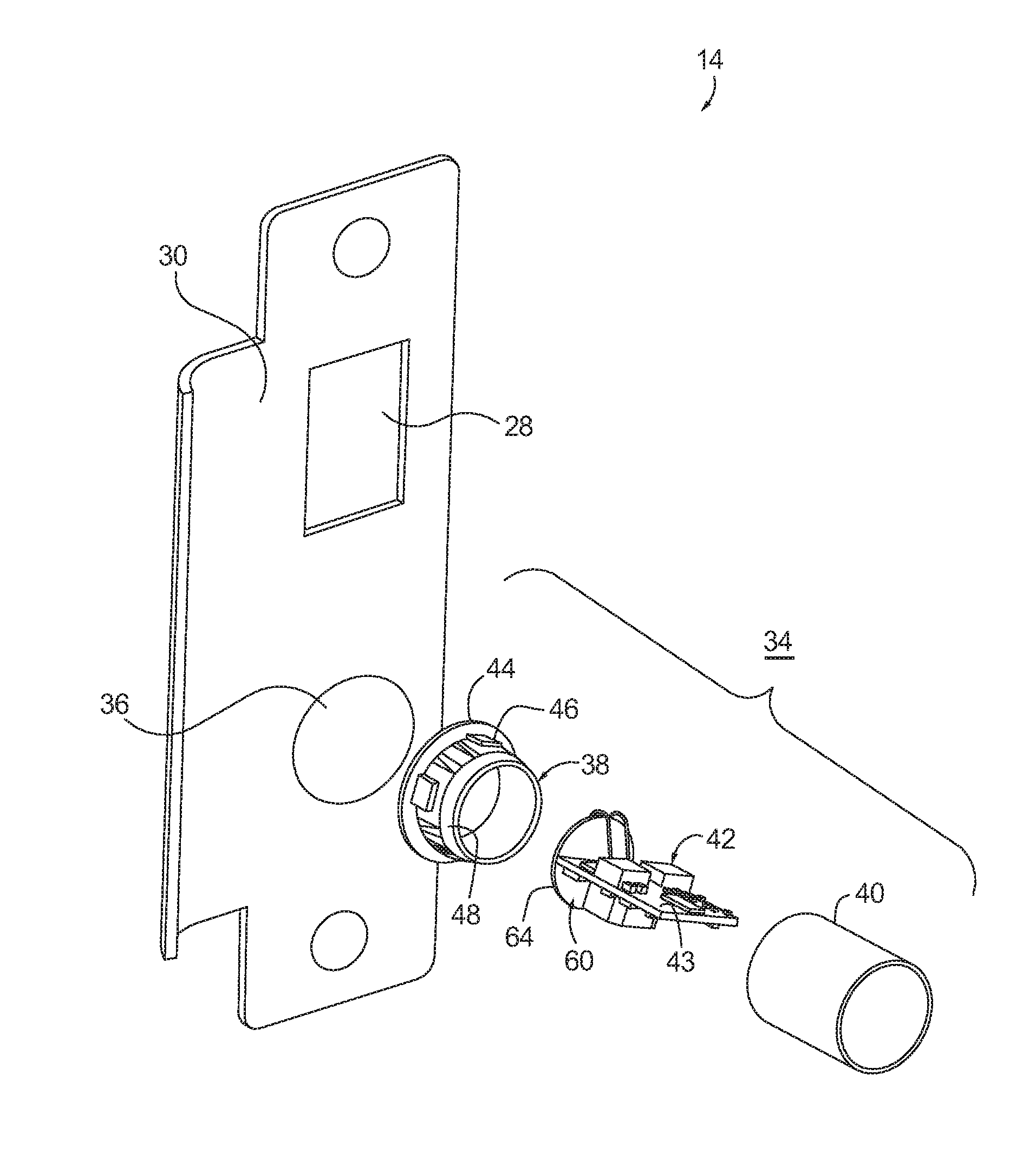
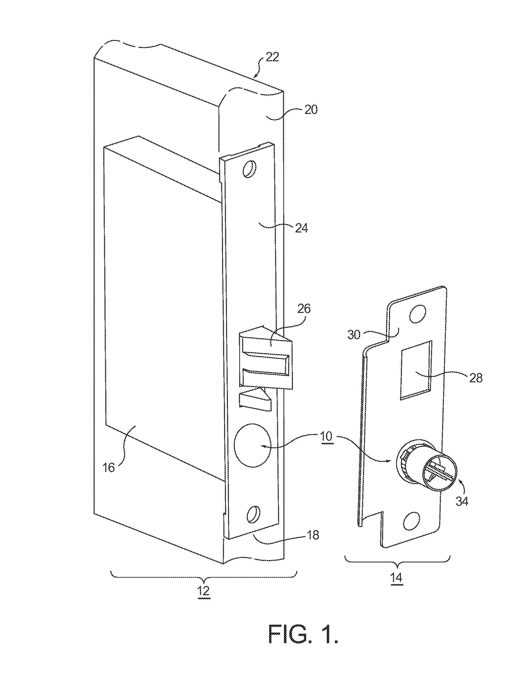
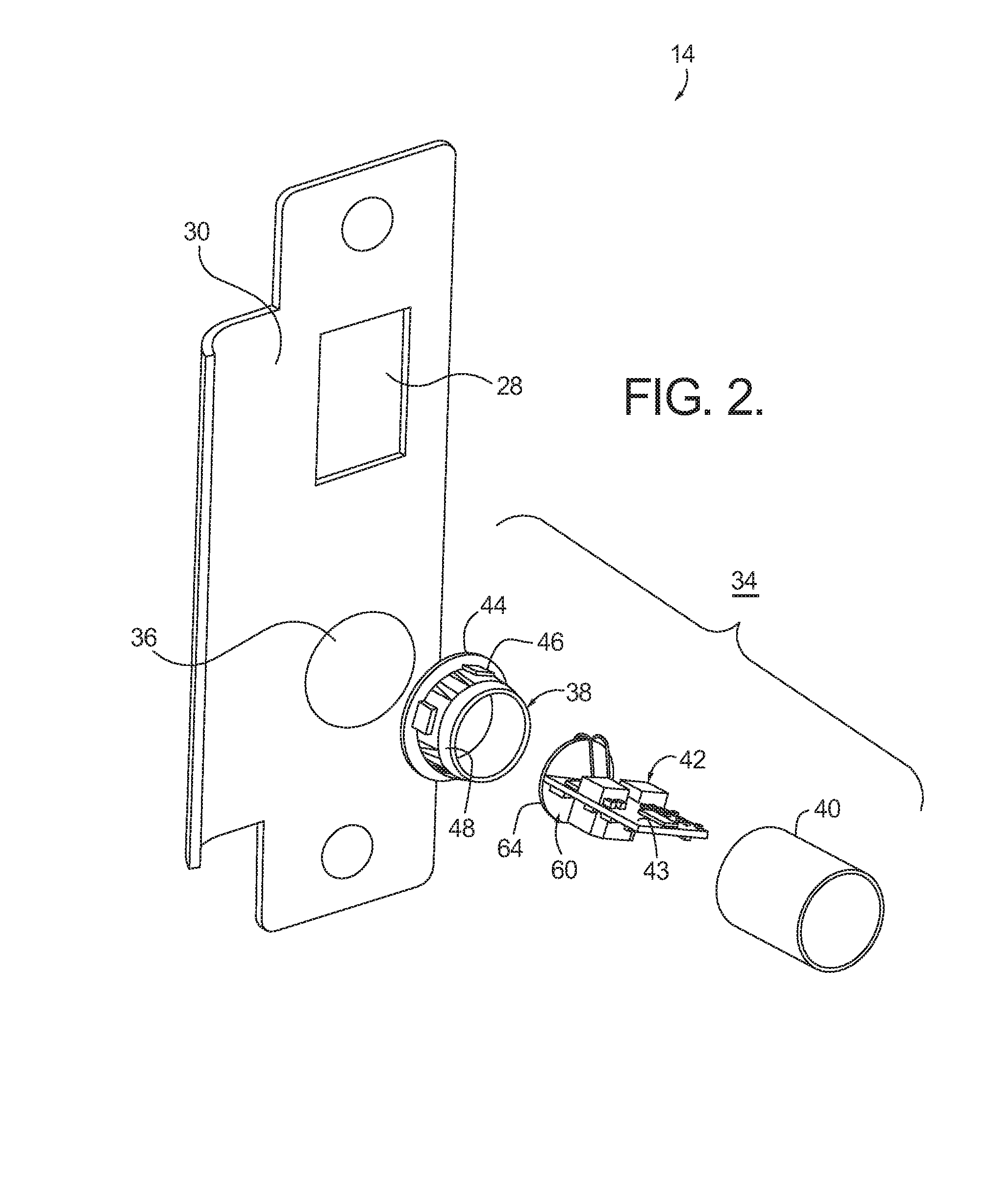
[0022]Referring to FIG. 1 through 4, an embodiment of a resonant inductive power coupling transfer system (hereinafter “power-transfer system”) is generally indicated by reference numeral 10. Power-transfer system 10 includes a first transformer portion 34 (FIG. 2) and a second transformer portion 32 (FIG. 3). In this embodiment, the power-transfer system 10 is substantially contained in a mortise lock set having a door unit 12 and a frame unit 14. However, it is under stood that power-transfer system 10 need not be contained within a lock set.

[0023]Door unit 12 generally includes a first object that is a lock body 16 in this embodiment. The lock body 16 is inserted within a mortise cut 18 into the edge 20 of a door 22, proportioned so as to create a friction fit between the lock body 16 and door 22. A face plate 24 covers any gaps between the lock body 16 and the face of edge 20 as well as protects the internal mechanisms housed within the lock body 16. Face plate 24 is generally a...


PUM


Abstract

What is presented is a power-transfer system that provides resonant inductive power from a first object to a second object, which is adjacent to the first object. The system includes a first transformer portion that is positioned on the first object and having a first core portion. The first core portion includes a transmit unit configured to transfer an electromagnetic field to the second transformer portion. The first core portion also includes first circuitry that allows the transmit unit to transfer the electromagnetic field. The second transformer portion is positioned on the second object and has a second core portion. The second core portion includes a receiver unit configured to receive the electromagnetic field. The second core portion also includes second circuitry that allows the transmit unit to transfer the electromagnetic field.

Description

CROSS-REFERENCE TO RELATED APPLICATIONS[0001]This application claims the benefit of U.S. Patent Application Ser. No. 62 / 147,397, filed Apr. 14, 2015, the contents of which are hereby incorporated by reference in its entirety.TECHNICAL FIELD[0002]The present invention relates to power-transfer devices and systems for providing a resonant inductive power coupling between a first object and a second object; more particularly, to such a device or system wherein said first and second objects are not physically connected electrically; and most particularly, to providing electric power to a lock mechanism for electrically locking or unlocking a door mounted in a frame via a transformer arrangement having a transmitter portion and a receiver portion. The transformer arrangement may reside in a mortise-type lock set having a latch electrically retained or released from its related strike or the transformer arrangement may reside in the edge of the door and adjacent surface of the door frame ...

Claims


Application Information

Patent Timeline
IPC IPC(8): H02J50/12B60L11/18E05B47/00H02J7/02
CPCH02J50/12H02J7/025E05B2047/0082E05B47/00B60L11/182E05B2047/0061B60L53/12Y02T10/70Y02T10/7072Y02T90/14
Inventor LEWIS, ROBERT W.HANCHETT, JR., LELAND J.
Owner HANCHETT ENTRY SYST
Why Eureka
Eureka Blog
Learn More