Pigtail for optimal aortic valvular complex imaging and alignment

a complex imaging and alignment technology, applied in the field of aortic valve complex imaging and/or transcatheter aortic valve replacement, can solve the problems of unreliability of imaging methods, increased risk of prolonged or permanent damage, need for further medical attention or dialysis, etc., and achieve the effect of facilitating precise rotational positioning

Active Publication Date: 2016-10-27
CEDARS SINAI MEDICAL CENT
View PDF6 Cites 14 Cited by
  • Summary
  • Abstract
  • Description
  • Claims
  • Application Information

AI Technical Summary

Benefits of technology

[0014]In an embodiment, the central lumen of the catheter is relatively large (for example, 8-24 Fr) and acts as a long delivery sheath for a balloon aortic valvuloplasty (BAV) balloon or TAVR delivery system. In a further embodiment, the device comprises a mechanism (for example, a radiographic maker) for aligning the ridges, lines, points or alternative markers of the central lumen and the BAV or TAVR delivery system to facilitate precise rotational positioning of the BAV or TAVR delivery system in relation to the three native aortic valve leaflets.

Problems solved by technology

Hence, this imaging method is unreliable, and may require multiple injections and large amount of contrast dye for completely visualizing the aortic root and determining the co-axial plane of radiographic projection.
Such patients are at a greater risk of prolonged or permanent damage from the dye, often resulting in the need for further medical attention or dialysis.
A focused and more precise delivery of contrast may also limit the patient's exposure to radiation.
Another challenging step during a TAVR procedure is to advance an instrument (e.g., a guidewire, a catheter, and / or a pressure sensor) across the aortic valve retrogradely from the aorta to the left ventricle.

Method used


Image

  • Pigtail for optimal aortic valvular complex imaging and alignment
  • Pigtail for optimal aortic valvular complex imaging and alignment
  • Pigtail for optimal aortic valvular complex imaging and alignment

Examples


example 1

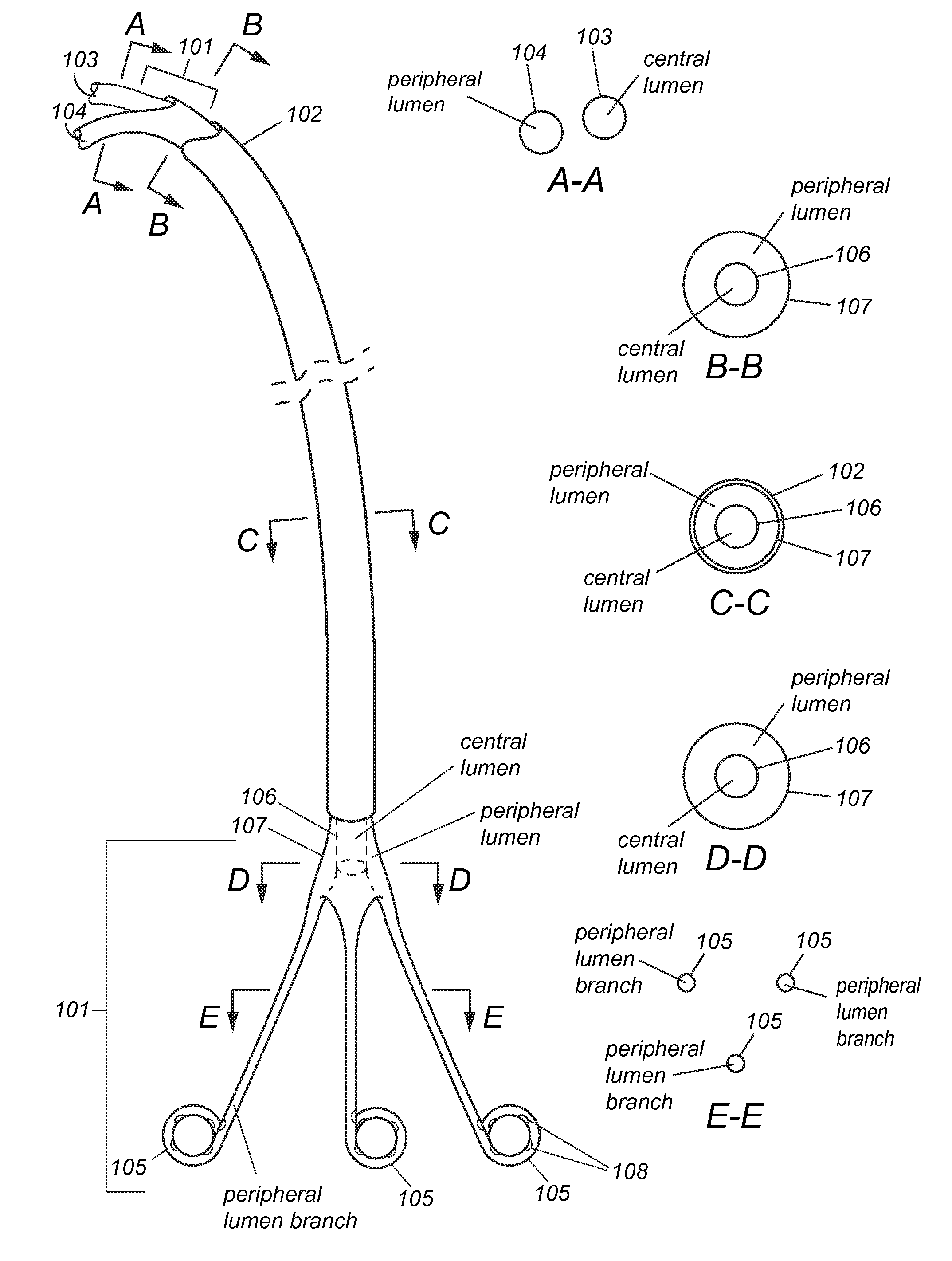
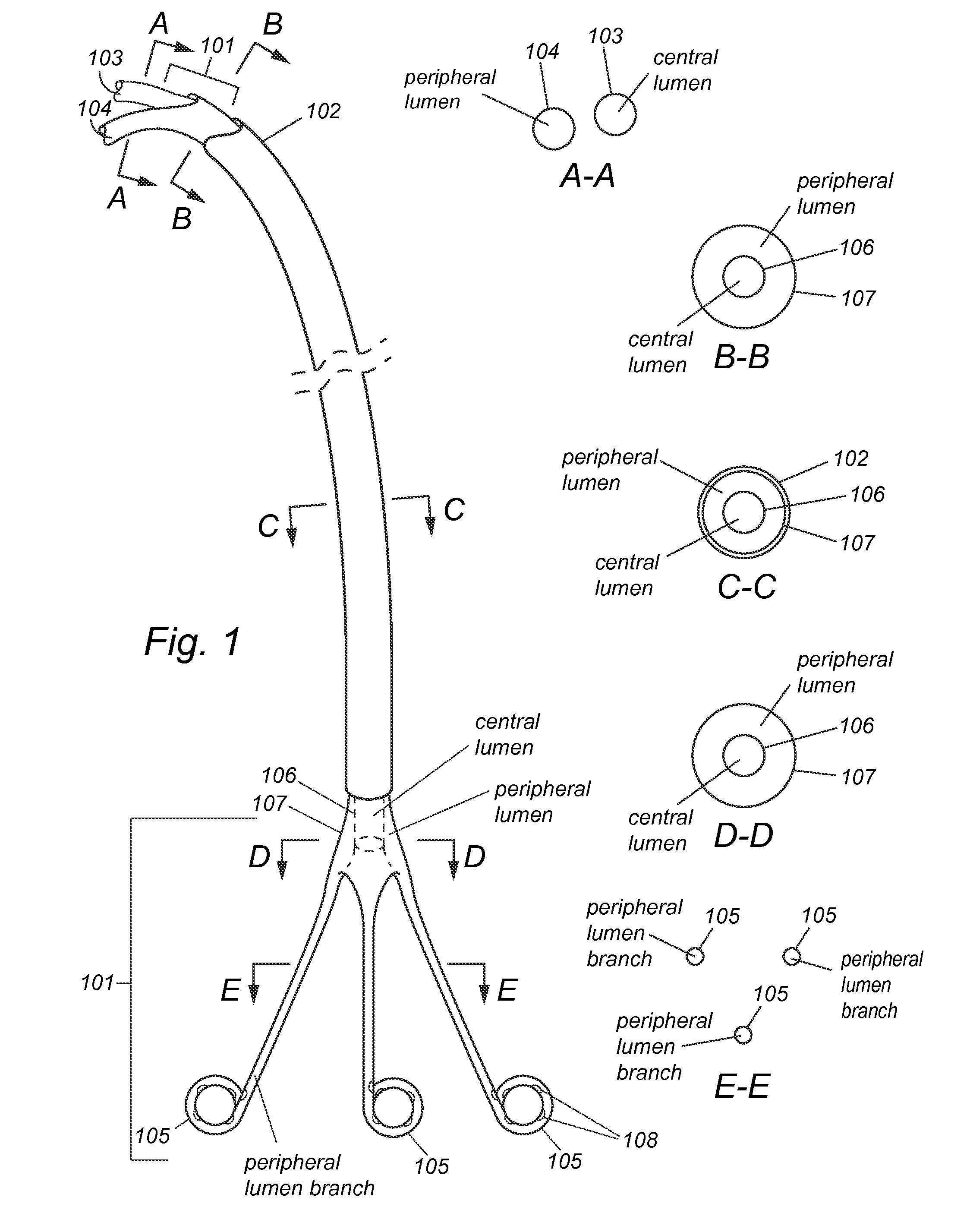
[0029]A non-limiting example of a device according to the present disclosure is shown in FIG. 1. The catheter 101 is covered by an outer sheath 102. The length of the catheter 101 may be but is not limited to about 90-300 cm depending on the precise application. The diameter of the catheter may be but is not limited to about 4-23 Fr. The length of the outer sheath 102 may be but is not limited to about 80-290 cm. The diameter of the outer sheath 102 may be but is not limited to about 5-24 Fr. The catheter 101 may have an interior wall 106 and an exterior wall 107. In some embodiments, a central lumen is defined by the interior wall 106 at the center of the catheter 101. The central lumen may be used for inserting another instrument (e.g., a guidewire, a catheter, and a pressure sensor). For example, the catheter 101 may be advanced over a guidewire in the central lumen to be guided to reach the sinotubular junction or other internal structure, or a guidewire may be inserted in the c...

example 2

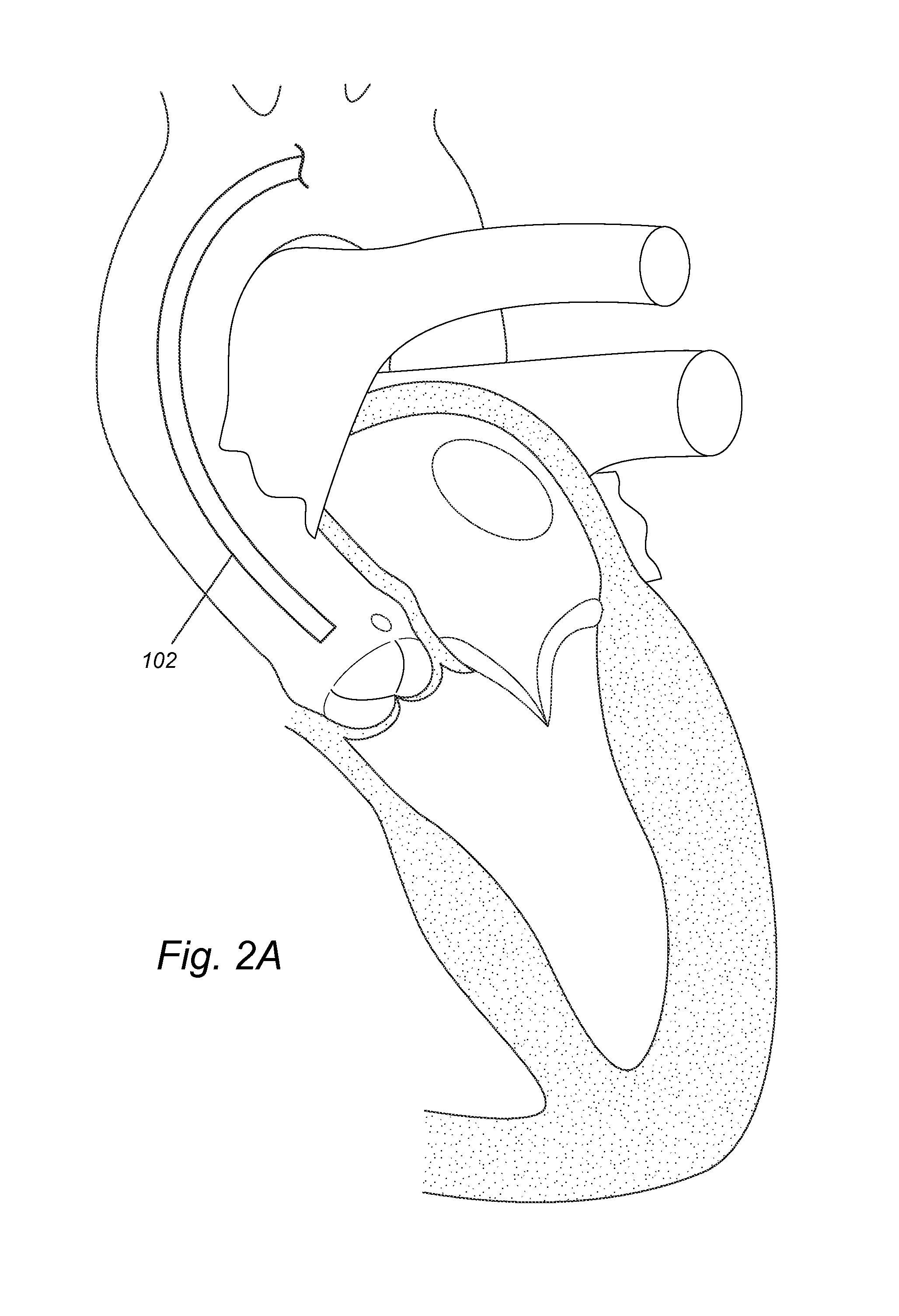
[0036]A non-limiting example of a method according to the present disclosure is shown in FIGS. 2A-E. In some embodiments, standard steps may be performed, including induction of anesthesia (local or general), sterile preparation and other necessary and standard steps in a transcatheter and percutaneous operation (for example, incising and / or pre-closing an artery, threading and / or removing a guidewire, and inserting and / or withdrawing a catheter). FIG. 2A illustrates an outer sheath 102 that has been maneuvered to reach the sinotubular junction of a subject via transfemoral, transaxillary / subclavian, or transaorticroute. Some routine steps are not shown or described here. For example, a guidewire may be mounted to the outer sheath's distal end to guide the outer sheath through the subject's vasculature system. Then, a catheter 101 may be inserted into the outer sheath 102. As the outer sheath 102 encloses the distal portion of the catheter 101, the three distal branches 105 are flat...

example 3

[0041]Another non-limiting example of the method is shown in FIGS. 3A-E. After induction of anesthesia, a caregiver may perform sterile preparation and other necessary and standard steps in a transcatheter and percutaneous operation (for example, incising and / or pre-closing an artery, threading and / or removing a guidewire, and inserting and / or withdrawing a catheter). As illustrated in FIG. 3A, an outer sheath 102 may be maneuvered to reach the sinotubular junction of a subject via transfemoral, transaxillary / subclavian, or transaortic route. Some routine steps are not shown or described here. For example, a guidewire may be mounted to the outer sheath's distal end to guide the outer sheath through the subject's vasculature system. A catheter 101 may then be inserted into the outer sheath 102 and advanced to the distal end of the outer sheath 102. As illustrated in FIG. 3B, while the outer sheath 102 encloses the distal portion of the catheter 101, the three distal branches 105 (in ...


PUM


Abstract

In various embodiments, provided herein are devices, systems and methods using two, three or more pigtails for precisely imaging an aortic valve complex with minimal contrast and/or for advancing an instrument, such as a wire, or device, such as a transcatheter valve, across an aortic valve. In various embodiments, these devices, systems and methods may be used to diagnose and/or treat patients with aortic stenosis, other valvular heart disease or other cardiovascular or non cardiovascular disease, facilitating precise contrast or drug or device delivery, precise pressure measurement and/or precise drainage or sampling. In some embodiments, each of the multiple pigtails of the device may be advanced independently of one another in multiple directions and at multiple lengths of deployment to optimize position.

Description

FIELD OF INVENTION[0001]This invention relates to devices, systems and methods for aortic valve complex imaging and / or for transcatheter aortic valve replacement, which may be used to diagnose and / or treat aortic valve diseases.BACKGROUND OF THE INVENTION[0002]All publications cited herein are incorporated by reference in their entirety to the same extent as if each individual publication or patent application was specifically and individually indicated to be incorporated by reference. The following description includes information that may be useful in understanding the present invention. It is not an admission that any of the information provided herein is prior art or relevant to the presently claimed invention, or that any publication specifically or implicitly referenced is prior art.Prior Transcatheter Valve Therapies[0003]Valvular heart disease is characterized by damage to or a defect in one of the four heart valves: the mitral, aortic, tricuspid or pulmonary. The mitral and...

Claims


Application Information

Patent Timeline
Patent Type & Authority Applications(United States)
IPC IPC(8): A61M25/00A61B5/055A61B8/08A61M25/01A61M5/00A61B5/00A61F2/24A61B6/03A61B6/00
CPCA61M25/0071A61B6/032A61B5/055A61B8/481A61B6/503A61M2025/0681A61M5/007A61B5/6857A61F2/2427A61M25/0108A61M25/007A61B8/0883A61B6/481A61M31/005A61B8/085A61B8/12
Inventor AL-JILAIHAWI, HASANIAN
Owner CEDARS SINAI MEDICAL CENT
Why Eureka
Try Eureka