Drive valve device based on capacitive sensing

a capacitive sensing and drive valve technology, applied in flushing devices, water installations, constructions, etc., can solve the problems of complex assembly, inconvenient, and inability to meet the needs of water-proof performance, so as to avoid water erosion, protect capacitive sensing control modules, and avoid water erosion

Active Publication Date: 2016-10-27
PENG DONG +1
View PDF4 Cites 0 Cited by
  • Summary
  • Abstract
  • Description
  • Claims
  • Application Information

AI Technical Summary

Benefits of technology

[0008]In another preferred embodiment, the assembly fixture is disposed in an overflow pipe of the drain valve or in a housing of the drain valve. The drain valve doesn't need other fixing structure to assemble the assembly fixture, the structure is compact with well applicability.
[0009]In another preferred embodiment, the capacitive sensing control module is disposed in a closed box, the closed box is connected to the assembly fixture. The closed box can efficiently protect the capacitive sensing control module that it avoids water erosion.
[0010]In another preferred embodiment, the external portion of the closed box is disposed with a rack, the assembly fixture comprises a fasten sleeve sleeved on the overflow pipe, a connecting set connected to the side of the fasten sleeve and a stop element to limit the vertical movement of the rack, the rack vertically passes through connecting set, the stop element is movably disposed to the connecting set to alternately lock to the rack or separate from the rack. The rack movably passes through the connecting set, it removes the limit of the stop element to the rack, so that the capacitive sensing control module can be height adjusted.
[0011]In another preferred embodiment, the capacitive sensing control module comprises a capacitive sensing component to sense a hand signal from the external portion of the water tank of the toilet to form a capacity variation sensing signal, an air pump connected to the capacitive sensing component to pump air to the drain valve through an air pipe based on the capacity variation sensing signal so as to open the drain valve and a battery component to supply power to the air pump. The drain valve is controlled by air, the structure is simpler. Moreover, the air control drain valve doesn't need other button operation component, no pipe or wire is needed to connect the upper cover of the water tank and the drain valve, the structure is simple, as the air pipe keeps still, it doesn't influence other components (for example the refill pipe) of the water tank.

Problems solved by technology

Therefore, existing drain valves has some defects: firstly, the drain valve and the button or sensing component need to be assembled separately, the assembly is complicated and inconvenient; secondly, for a sensing type drain valve, the electric wires are exposed out of the structure and located in the water tank, it goes against the water proof performance.
However, different ceramic water tank have different wall thickness, not all sensing control component can be hung to the wall, so that it is not suitable for all; besides, as different water tanks have different height, the chain needs to be height adjusted, the assembly is complicated; and as the flapper is located at the center of the water tank, the sensing control component needs to be hung at the center, but when the flapper is open, it blocks at the front of the water tank, thus influencing the sensing operation.

Method used


Image

  • Drive valve device based on capacitive sensing
  • Drive valve device based on capacitive sensing
  • Drive valve device based on capacitive sensing

Examples


first embodiment

The First Embodiment

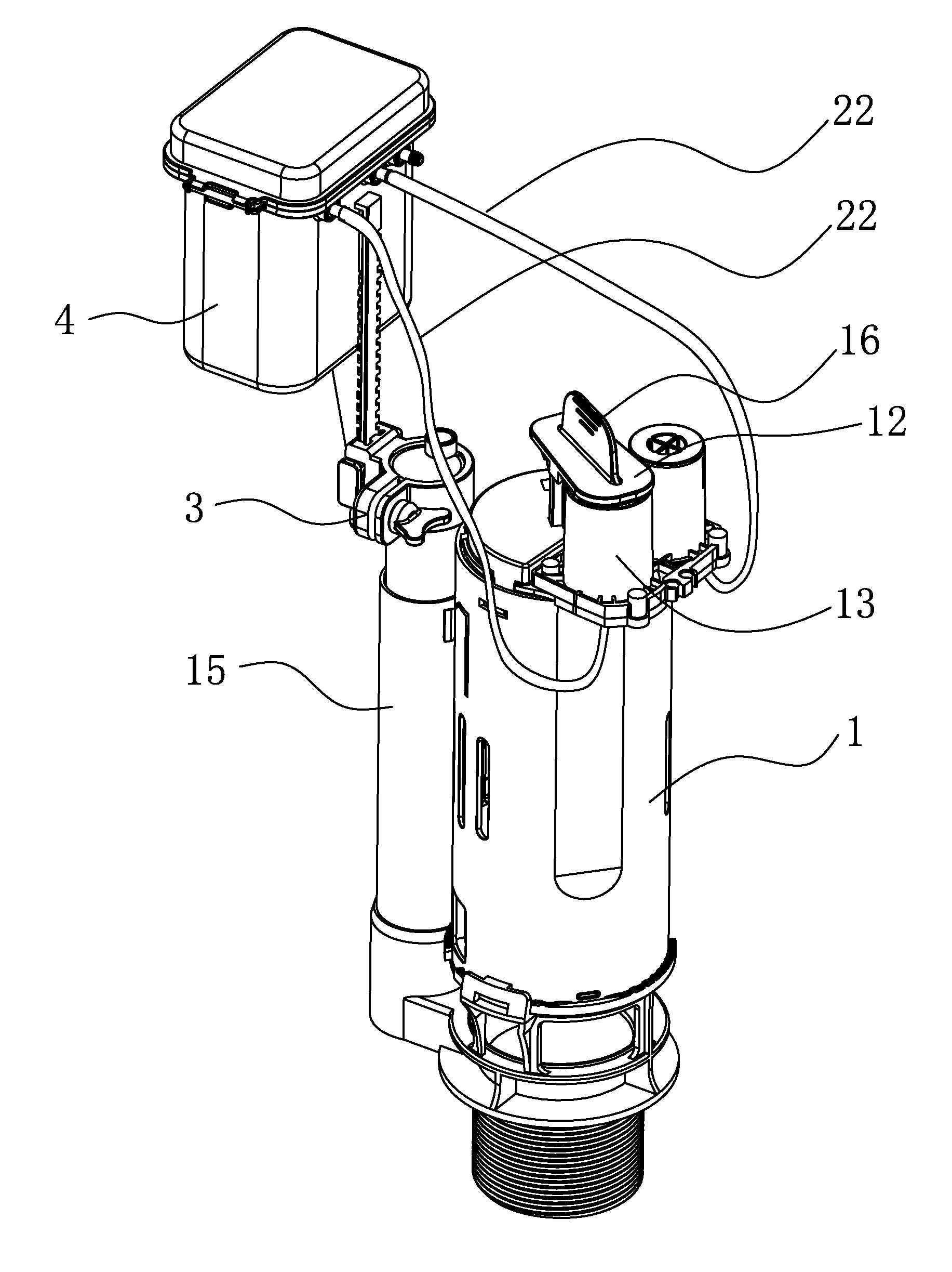
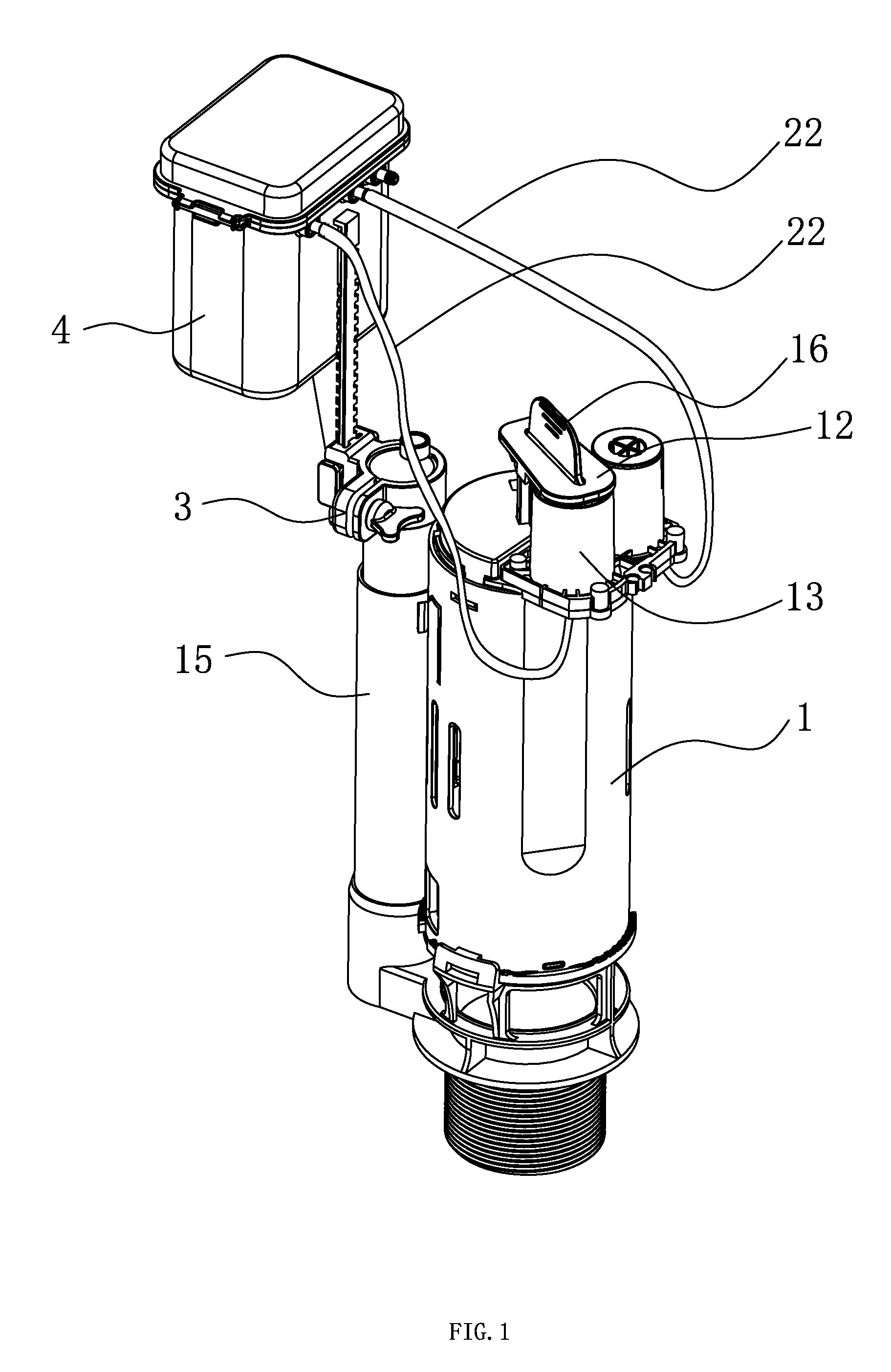
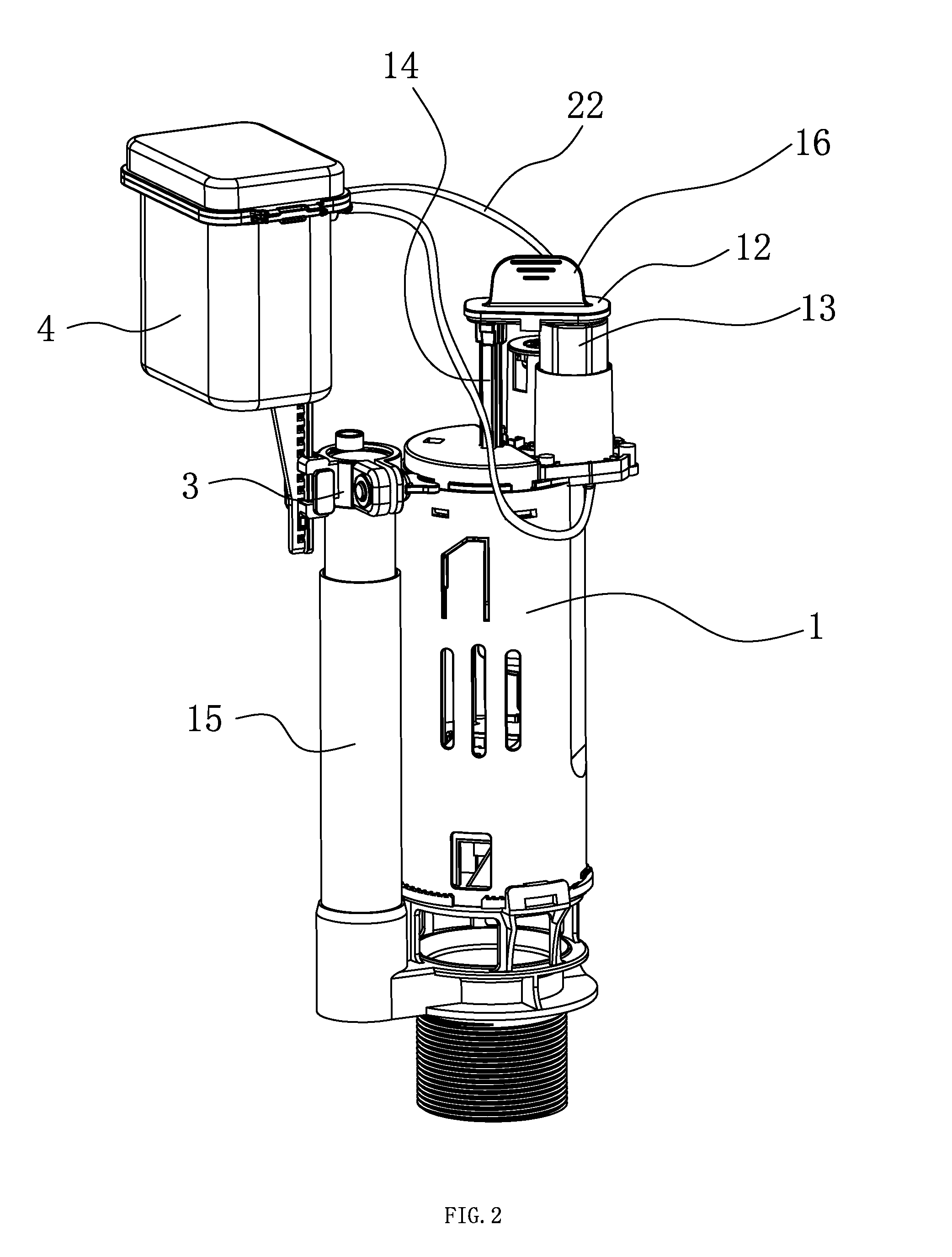
[0037]Referring to FIGS. 1-5, the drain valve device based on capacitive sensing comprises a drain valve 1 disposed in the toilet water tank 5 to control the water tank 5 to flush the toilet seat 6; a capacitive sensing control module 2 used to open the drain valve 1, the capacitive sensing control module 2 is disposed in a closed box 4; an assembly fixture used to connect the capacitive sensing control module 2 to the drain valve 1, the closed box 4 is connected to the assembly fixture 3.

[0038]The drain valve 1 is an air control drain valve, the drain valve 1 is disposed with a pulling bar 14 used to open the toilet water tank 5, the top portion of the pulling bar 14 is connected to one end of a pressing plate 12, the other end of the pressing plate 12 is connected to a telescopic pipe 13, both ends of which are respectively connected to the pressing plate 12 and the housing of the drain valve 1. The drain valve 1 is further disposed with an air bag located in t...

second embodiment

The Second Embodiment

[0042]Referring to FIG. 6, the drain valve device of the second embodiment differs from the first embodiment in that: the assembly fixture is connected to the housing 18 of the drain valve 1, the assembly fixture comprises a connecting set 32a integratedly formed with the housing 18, a stop element 33 used to limit the vertical movement of the rack 41a. The rack 41 a vertically passes through the connecting set 32a, the stop element 33 is movably connected to the connecting set 32a to alternately locked to the rack 41 a and separate from the rack 41a.

[0043]It should be noted that, the drain valve can be applied with a mechanical drain valve, when the capacitive sensing control module detects a hand signal, it drives the motor to work, the drain valve drains water by pulling a chain or a cord.


PUM


Abstract

The present invention is provided with a drain valve device based on capacitive sensing, comprising a drain valve disposed in the water tank of the toilet to control the water tank to drain water, wherein further comprising a capacitive sensing control module used to open the drain valve and an assembly fixture used to connect the capacitive sensing control module to the drain valve to make the capacitive control module and the drain valve form an integration. The assembly fixture connects the capacitive sensing control module and the drain vale to form an integration, when assembling, it only needs to assemble the drain valve that it can, at the same time, fix the capacitive sensing control module to the toilet water tank, the assembly is simple and convenient. It doesn't need to dispose assembly hole in the water tank cover, the structure is simpler.

Description

FIELD OF THE INVENTION[0001]The present invention relates to a drain valve device of the toilet water tank, especially to a drain valve device based on capacitive sensing.BACKGROUND OF THE INVENTION[0002]The drain valve used in the ceramic toilet water tank in the existing market is usually coupled a button or a sensing window of the water tank cover to form a mechanical type, hydraulic type, sensing type or air control drain valve, the drain valves are needed to connect to the button or the sensing component in other places, such as in the water tank cover, by pushing bars or electric wires or pipes, when assembling, it needs to assemble the button or the sensing component after the drain valve is assembled. Therefore, existing drain valves has some defects: firstly, the drain valve and the button or sensing component need to be assembled separately, the assembly is complicated and inconvenient; secondly, for a sensing type drain valve, the electric wires are exposed out of the str...

Claims


Application Information

Patent Timeline
Patent Type & Authority Applications(United States)
IPC IPC(8): E03D5/10E03D1/34
CPCE03D1/34E03D5/105E03D1/00E03D5/10
Inventor WU, GUOQIANGDAI, ZHENYU
Owner PENG DONG
Why Eureka
Try Eureka