Temperature monitoring of subject bodies using wireless energy transfer

a wireless energy transfer and subject body technology, applied in the field of electronic methods and systems for sensing and monitoring the temperature of subjects, can solve the problems of large human health and money losses, loss that can easily translate into thousands of lost human lives and hundreds of millions of dollars of losses, and significant limitations

Active Publication Date: 2016-10-27
UNITED ARAB EMIRATES UNIVERSITY
View PDF4 Cites 3 Cited by
  • Summary
  • Abstract
  • Description
  • Claims
  • Application Information

AI Technical Summary

Benefits of technology

[0021]As a first aspect of the invention, there is provided a temperature sensing device for measuring temperature of a subject body and relaying the measured temperature to a control device remote from the temperature sensing device. The temperature sensing device comprising a resonant receiver circuit is designed to receive resonant wireless power loads from the control device; a temperature sensor adapted to be operat...

Problems solved by technology

However, due to inefficiencies in storage and transport renders a significant percentage of these valuable vaccines ineffective resulting in huge losses in terms of human health and money.
Such losses can easily translate into thousands of lost human lives and hundreds of millions of dollars of losses due to ineffective treatment and the consequential medical costs.
However, there is a significant limitation.
However, these technologies are cumbersome, and most importantly, the technologies embodied cannot be integrated on a single chip.
The electronic system described in the cited patent, due to its complexity, requires large source of power.
Alternatively these electronic systems would use visible or infrared source of energy (solar cell) that cannot be integrated on a single chip, due to the use of a mix of technologies; thus the size of the electronic tag is larger ...

Method used


Image

  • Temperature monitoring of subject bodies using wireless energy transfer
  • Temperature monitoring of subject bodies using wireless energy transfer
  • Temperature monitoring of subject bodies using wireless energy transfer

Examples


Embodiment Construction

[0047]The foregoing descriptions of specific embodiments of the present disclosure have been presented for purposes of illustration and description. They are not intended to be exhaustive or to limit the invention to the precise forms disclosed, and obviously many modifications and variations are possible in light of the above teaching. The exemplary embodiment was chosen and described in order to best explain the principles of the invention and its practical application, to thereby enable others skilled in the art to best utilize the invention and various embodiments with various modifications as are suited to the particular use contemplated. The terms “a” and “an” herein do not denote a limitation of quantity, but rather denote the presence of at least one of the referenced item.

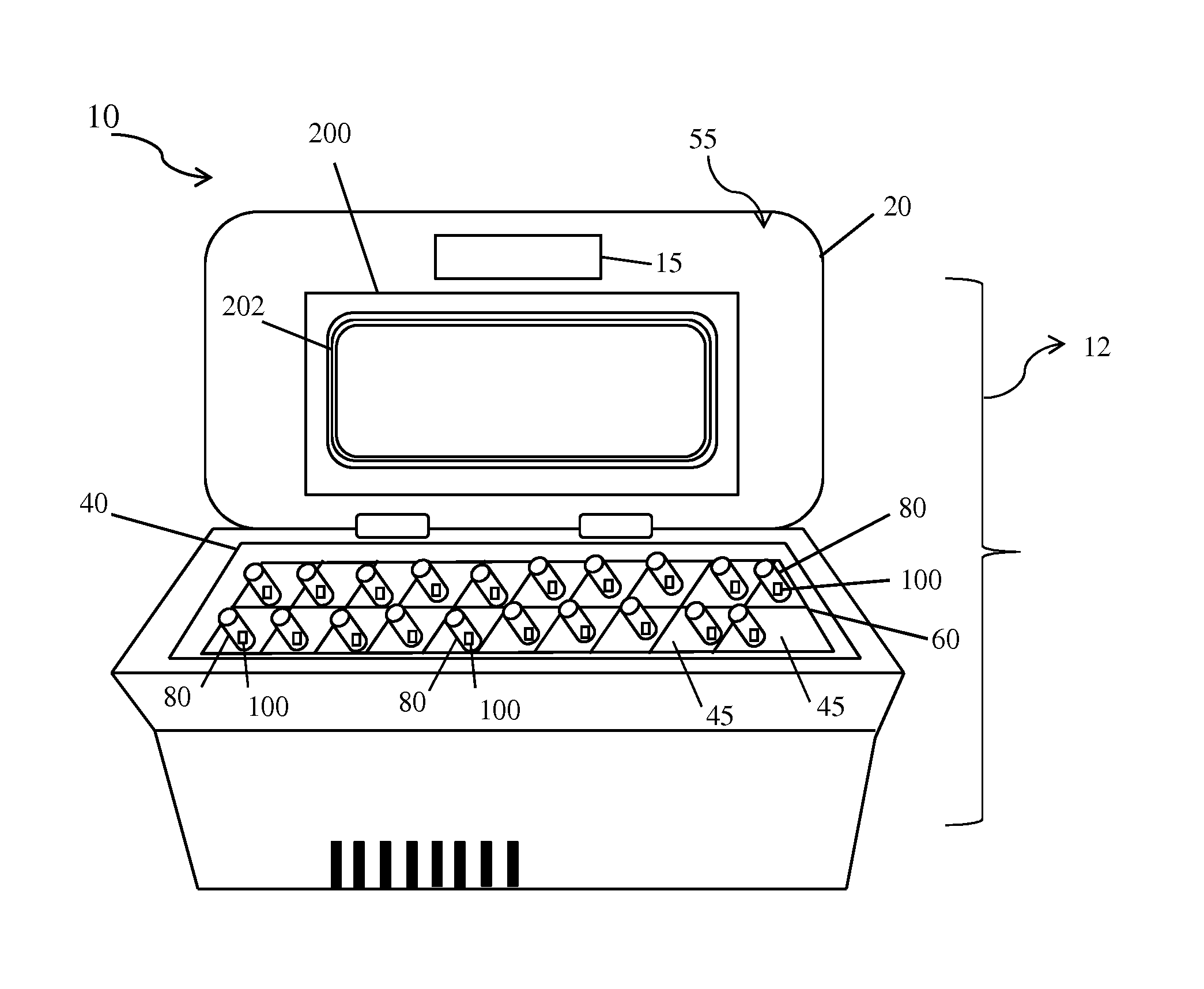
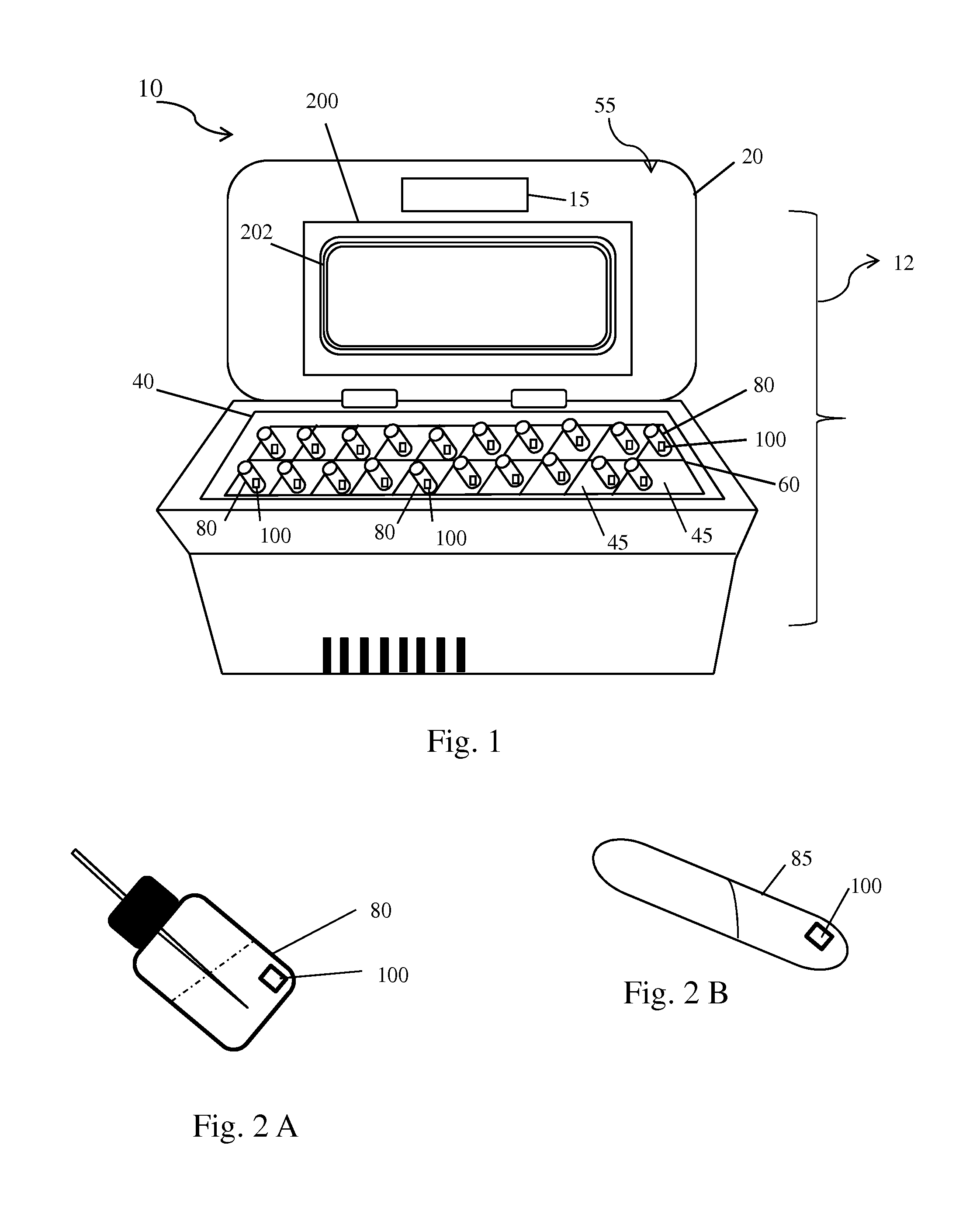
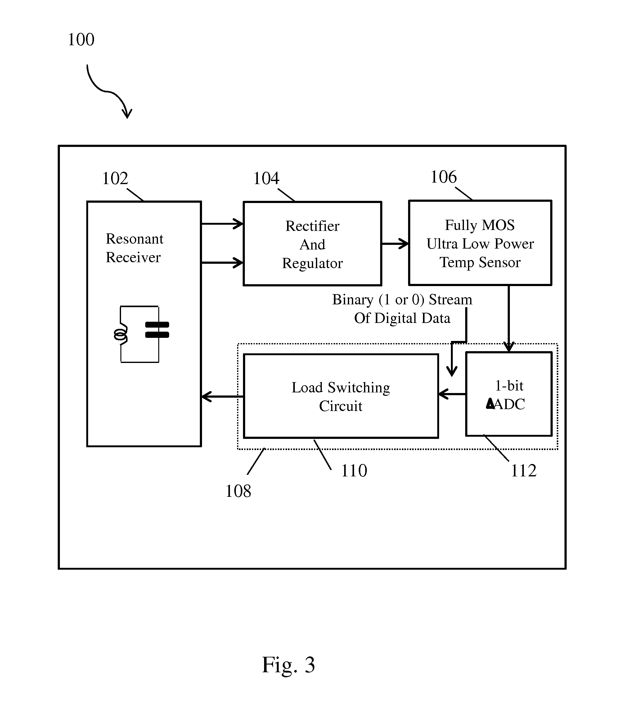
[0048]As a first aspect of the invention (see FIGS. 1-3), the present invention provides a temperature-sensing device 100 adapted to be in physical contact with a subject body 80 (for example, immersed in ...


PUM


Abstract

Provided is a system for monitoring temperature of one or more subject bodies, the system comprising a resonant reading circuit adapted to generate resonant wireless power loads; a resonant receiver circuit adapted to be magnetically connected to the resonant reading circuit for receiving the resonant wireless power loads and for generating power based on the power loads received; one or more temperature sensors adapted to be operatively connected to the resonant receiver circuit for deriving power and for measuring the temperatures of the one or more subject bodies respectively based on the resonant wireless power loads received; and a relay circuit adapted to be operatively connected to the one or more temperature sensors and to the resonant receiver circuit for relaying the measured temperatures to the resonant reading circuit via the resonant receiver circuit using wireless resonant energy transfer. There is further provided a temperature-sensing device and a storage apparatus.

Description

FIELD OF THE DISCLOSURE[0001]The present disclosure generally relates to an electronic method and system for sensing and monitoring the temperature of subject bodies, and particularly to a temperature monitoring apparatus and system for sensing and monitoring temperature of vaccines.BACKGROUND OF THE DISCLOSURE[0002]Use of vaccine to control and prevent the disease is a vital part of modern human life. However, due to inefficiencies in storage and transport renders a significant percentage of these valuable vaccines ineffective resulting in huge losses in terms of human health and money.[0003]According to a recent meta-analysis published in the journal Vaccine that included studies published in more than 20 countries, it is estimated that a whopping 14 percent (%) to 35% of vaccines are damaged due to temperature excursions beyond the recommended limits during transportation or storage. Such losses can easily translate into thousands of lost human lives and hundreds of millions of d...

Claims


Application Information

Patent Timeline
IPC IPC(8): G01K1/02G01K7/01
CPCG01K7/01G01K1/024G01K1/026G01K7/32H02J50/12
Inventor RAMZAN, RASHADBEG, AZAMBASTAKI, NABIL
Owner UNITED ARAB EMIRATES UNIVERSITY
Why Eureka
Try Eureka