

Variable thickness diaphragm for a wideband robust piezoelectric micromachined ultrasonic transducer (PMUT)
a micro-machined piezoelectric micro-machined ultrasonic transducer, wideband technology, applied in piezoelectric/electrostrictive/magnetostrictive devices, mechanical vibration separation, instruments, etc., can solve problems such as output pressure and bandwidth compromise, and achieve enhanced pmut design, bandwidth and other enhanced operating characteristics, and increase resonant frequency control
- Summary
- Abstract
- Description
- Claims
- Application Information
AI Technical Summary
Benefits of technology
Problems solved by technology
Method used
Image

Examples
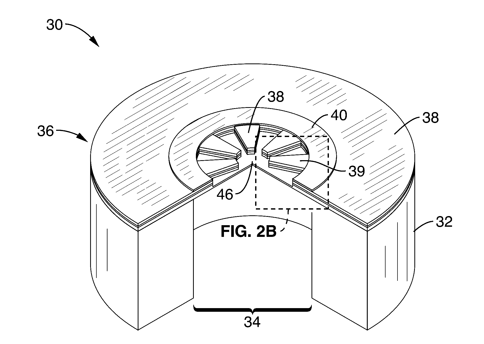
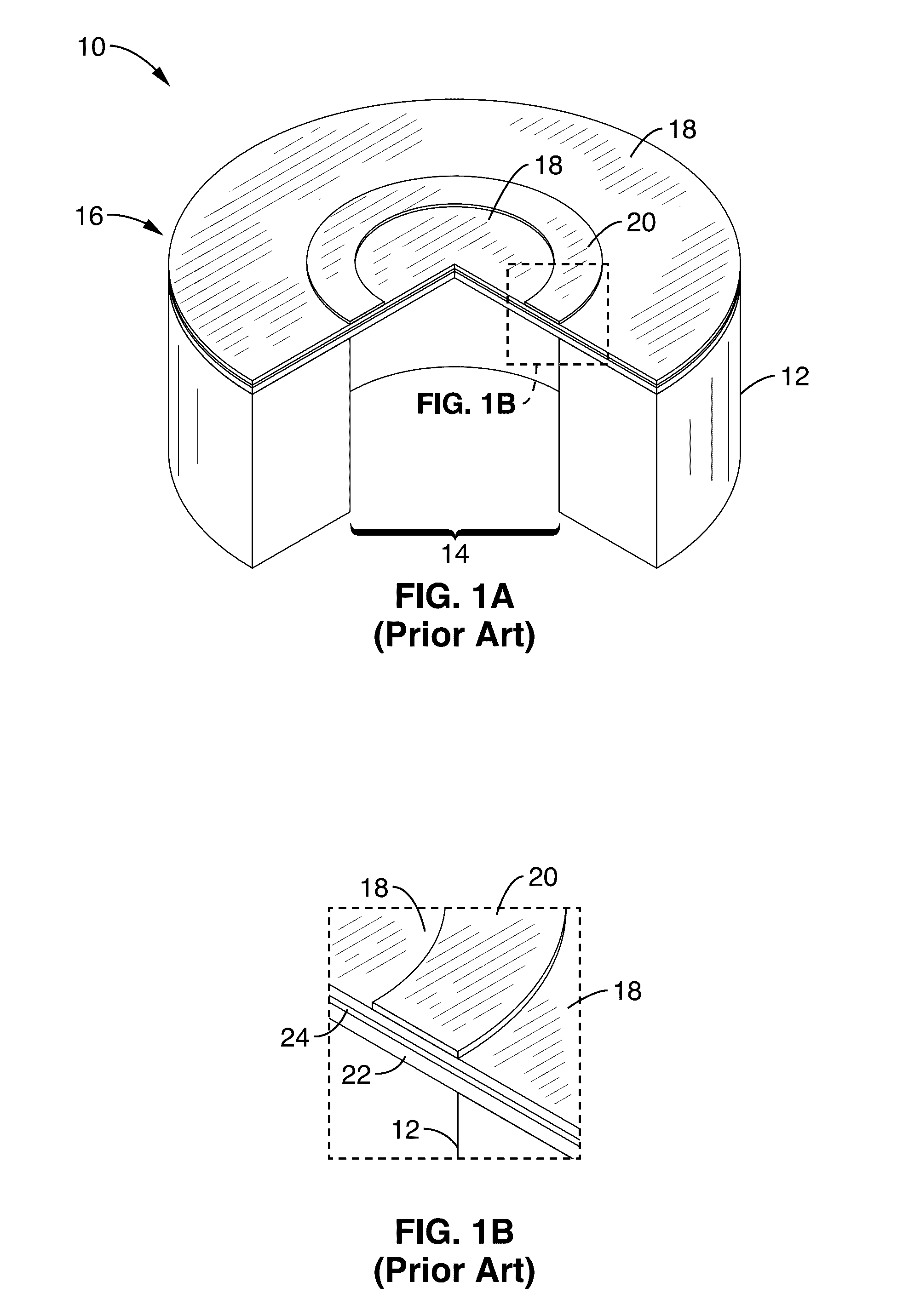
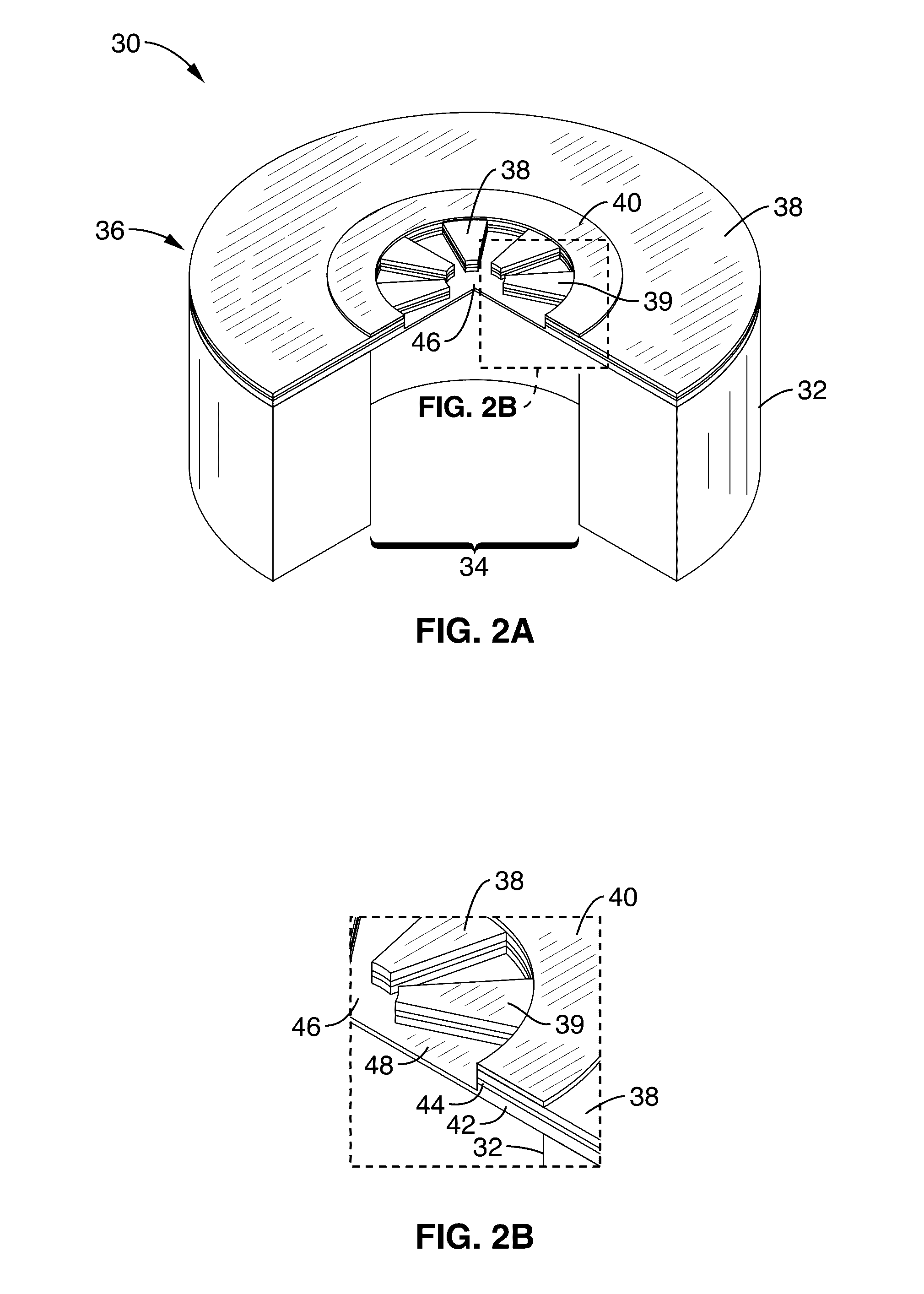
embodiment 10
[0037]FIG. 1A through FIG. 1B illustrate an embodiment 10 of a reference design, denoted herein as ‘design 0’ having a support structure (handle) 12, backside tube 14, flat constant-thickness diaphragm 16 configured with a top piezo surface 18. In the figure, one sees this piezo surface continuing on both sides beneath a top electrode 20. The diaphragm 16 is shown in FIG. 1B to comprise a passive elastic layer 22, over which is a metal layer 24, upon which piezo layer 18 is disposed. The diaphragm thickness is uniform except for the material of deposited top electrode 20.
[0038]The diaphragm has mass m0, stiffness k0 and damping b0 which are a function of the diaphragm area A0 and thickness t0:
m0∝A0t0
b0∝A0
k0∝t03 / A0 (3)
[0039]Therefore, the center frequency ω0 and bandwidth Δω0 are:
ω0∝t0A0Δω0∝1t0.(4)
[0040]Stress is known to result in variations in the effective stiffness of the diaphragm, which in turn results in changes in the center frequency ω0 in much the same way that tension ...
embodiment 50
[0049]In FIG. 3 a patterned square PMUT embodiment 50 is shown with handle 52, backside tube 54, patterned diaphragm 56 configured with a piezo layer 58 beneath a square shaped top electrode 60. It can be seen that material is removed from the center 62, and in radial sections 64, leaving protruding rib sections 59, which are the only portions containing piezo layer 58 within the interior of the top electrode. In this example, one rib (e.g., isosceles trapezoid) is shown extending from each of the sides of the square 60 perimeter.
embodiment 70
[0050]In FIG. 4 a patterned hexagonal PMUT embodiment 70 is shown with handle 72, backside tube 74, patterned diaphragm 76 configured with a piezo layer 78 beneath a hexagon-shaped top electrode 80. It can be seen that material is removed from the center 82, and in radial sections 84, leaving protruding rib sections 79, which are the only portions containing piezo layer 78 within the interior of the top electrode. In this example one rib (e.g., isosceles trapezoid) is shown extending from each of the sides of the hexagon 80 perimeter, although this is not a limitation of any of the embodiments. It should be appreciated that the above PMUTs are examples of devices which are radially symmetric. The present disclosure however, applies not only to any radially symmetric form, but to other forms / shapes as well.
PUM
 Abstract
Description
Claims
Application Information