Wiring thin plate having aerial wiring portion and method of manufacturing the same

Active Publication Date: 2016-10-27
NHK SPRING CO LTD
View PDF11 Cites 1 Cited by
  • Summary
  • Abstract
  • Description
  • Claims
  • Application Information

AI Technical Summary

Benefits of technology

The present invention provides a wiring thin plate that can reduce rigidity while preventing deterioration of electrical characteristics and variation in wiring thickness. The wiring traces in the aerial wiring portion are joined together without a base layer between them, and are supported by aerial base layers that are separate from each other. The aerial base layers are connected together with the aerial cover layer, which prevents deformation and variation in wiring intervals. This structure also prevents variation in wiring thickness.

Problems solved by technology

In the case where the metal substrate is thinned, however, rigidity contribution ratio of a wiring part formed on the metal substrate relatively increases to make it difficult to control the rigidity around the tongue of the flexure.
These related arts, however, hardly reduce the rigidity contribution ratio of the wiring part.
This, however, has a limit on reduction of rigidity even by partly removing the cover insulating layer because the cover insulating layer has the thickness of about 3 μm in general.
This structure, however, tends to cause deformation of the wiring traces and vary the wiring intervals, thereby to deteriorate an electrical characteristic.
Such a problem is occurred at not only the outrigger but also another aerial wiring portion of a tail portion of the flexure or of a part other than the flexure.

Method used


Image

  • Wiring thin plate having aerial wiring portion and method of manufacturing the same
  • Wiring thin plate having aerial wiring portion and method of manufacturing the same
  • Wiring thin plate having aerial wiring portion and method of manufacturing the same

Examples


first embodiment

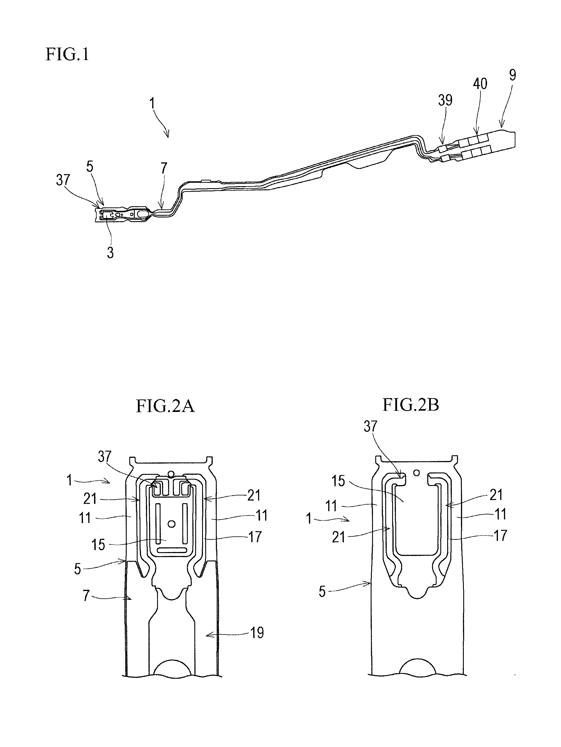
[0045]Hereinafter, a general configuration of a flexure according to the present invention will be explained with reference to FIGS. 1 to 2B.

[0046]FIG. 1 is a plan view schematically illustrating a flexure according to the first embodiment of the present invention, FIG. 2A is a plan view illustrating aerial wiring portions and their periphery of the flexure of FIG. 1 and FIG. 2B is a back view illustrating the same. In the following explanation, “right” and “left” mean both sides in a lateral direction orthogonal to a longitudinal direction of the flexure, “up” and “down” mean both sides in a thickness direction of the flexure, and “front” and “rear” mean a tongue side and a tail side of the flexure in the longitudinal direction, respectively.

[0047]The flexure 1 illustrated in FIG. 1 is an example of the wiring thin pate that is attached to a load beam of a head suspension installed in, for example, a hard disk drive for a computer. A front end of the flexure 1 supports a slider 3 t...

second embodiment

[0102]As illustrated in FIG. 7, the aerial wiring portion 21B has a link 27Bb provided to the aerial cover layer 27Ba. The link 27Bb is integrated with the aerial cover layer 27Ba and extends to the outrigger 11 of the metal substrate 5 as a supporting layer in a direction along which the wiring traces 25a, 25b, and 25c are arranged side by side. In FIG. 7, only the left outrigger 11 and the left aerial wiring portion 21B are indicated. The right outrigger 11 and the right aerial wiring portion 21B are omitted. The right and left outriggers and aerial wiring portions are symmetric.

[0103]According to the embodiment, the outrigger 11 has an outrigger base layer 23d that is formed together with the aerial base layers 23a, 23b, and 23c. From an inner side face of the outrigger base layer 23d to a top face of the same, the link 27Bb is formed so as to trace and coat the top face and the inner side face of the outrigger base layer 23d. The inner side face of the outrigger base layer 23d ...

third embodiment

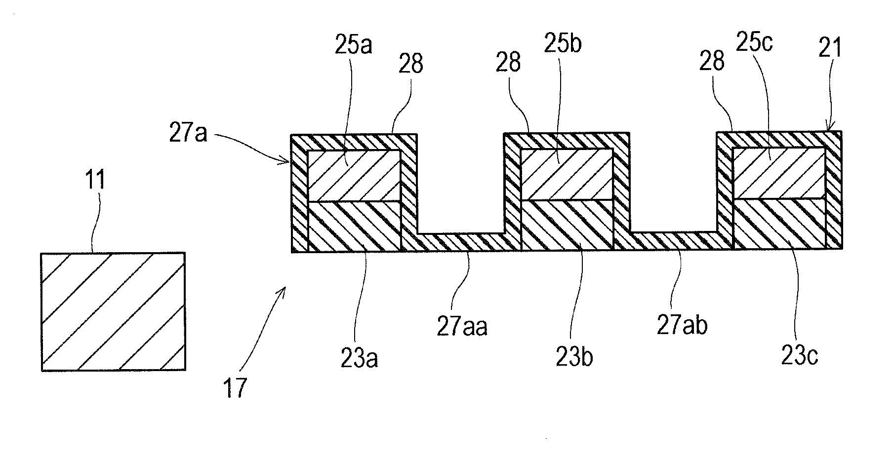
[0113]As illustrated in FIG. 9, the aerial wiring portion 21C has openings 27Cca, 27Ccb, and 27Ccc formed through the aerial cover layer 27Ca for the respective wiring traces 25a, 25b, and 25c. The openings 27Cca, 27Ccb, and 27Ccc opens respective top faces of the wiring traces 25a, 25b, and 25c to form top-face-exposed portions 25aa, 25ba, and 25ca on the wiring traces 25a, 25b, and 25c.

[0114]The openings 27Cca, 27Ccb, and 27Ccc longitudinally extend along the entire length of the wiring traces 25a, 25b, and 25c. The openings 27Cca, 27Ccb, and 27Ccc, however, may be formed on a plurality of portions along the wiring traces 25a, 25b, and 25c at longitudinal intervals or may be formed on a suitable portion for controlling the rigidity in the routing direction.

[0115]The top-face-exposed portions 25aa, 25ba, and 25ca has plated layers 61a, 61b, and 61c to cover the respective wiring traces 25a, 25b, and 25c for corrosion prevention.

[0116]As illustrated in FIG. 10, the method of manuf...


PUM


Abstract

Provided is a wiring thin plate capable of suppressing deterioration of an electric characteristic and variation in thickness of an aerial wiring portion while advancing reduction of rigidity of the aerial wiring portion. The wiring thin plate includes an aerial wiring portion including wiring traces and passing over an airspace, aerial base layers provided at the respective wiring traces in the aerial wiring portion and being apart from each other, and an aerial cover layer provided in the aerial wiring portion and spanning from the wiring traces of the aerial wiring portion through the aerial base layers to interspaces between adjacent aerial base layers of said aerial base layers.

Description

BACKGROUND OF THE INVENTION[0001]1. Field of the Invention[0002]The present invention relates to a wiring thin plate applied to a flexure of a head suspension or the like and a method of manufacturing the wiring thin plate.[0003]2. Description of Related Art[0004]A hard disk drive incorporates hard disks that are provided so as to rotate at high speed and head suspensions with sliders that are slightly lifted from the respective hard disks to write / read data to and from the hard disks. Each head suspension has a flexure through which the slider is attached to the head suspension. The flexure includes a wiring part formed on a metal substrate. A front end of the metal substrate is provided with a tongue onto which the slider is attached.[0005]Recent hard disks have high recording density, and therefore, the slider of the head suspension is required to make a flying height lower. In order to stabilize the low flying height, it is important to control rigidity of the metal substrate an...

Claims


Application Information

Patent Timeline
IPC IPC(8): H05K1/02H05K3/02H05K3/46
CPCH05K1/0298H05K3/02H05K3/4673H05K3/4652G11B5/60H05K1/028H05K2201/053H05K1/056H05K3/28H05K2201/09872H05K2203/0323G11B5/484G11B5/486G11B5/4853
Inventor YAMADA, YUKIE
Owner NHK SPRING CO LTD
Why Eureka
Try Eureka