Accommodating intraocular lens device

Active Publication Date: 2016-11-03
LENSGEN INC
View PDF5 Cites 62 Cited by
  • Summary
  • Abstract
  • Description
  • Claims
  • Application Information

AI Technical Summary

Benefits of technology

[0007]The intraocular lens (IOL) device described herein generally comprise two lens portions. In a preferred embodiment, a first lens portion provides most, if not all, of the accommodative power and a second base lens provides most, if not all, of the corrective refractive power that is needed by a particular patient. Because the first lens portion must provide an accommodative power, it must respond by either changing shape or by displacement along an optical axis in response to the contraction and relaxation of the ciliary muscles which control the eye's natural ability to accommodate. To that end, the first lens portion may be provided as an elastically deformable lens chamber that is filled with a fluid

Problems solved by technology

As conventional IOL devices are primarily focused for distance visions, they fail to correct for presbyopia and reading glasses are still required.
Thus, while patients who undergo a standard IOL implantation no longer experience clouding from cataracts, they are unable to accommodate, or change focus from near to far, from far to near, and to distances in between.
Despite the success of LASIK i

Method used


Image

  • Accommodating intraocular lens device
  • Accommodating intraocular lens device
  • Accommodating intraocular lens device

Examples


Embodiment Construction

[0053]Specific, non-limiting embodiments of the present invention will now be described with reference to the drawings. It should be understood that such embodiments are by way of example and are merely illustrative of but a small number of embodiments within the scope of the present invention. Various changes and modifications obvious to one skilled in the art to which the present invention pertains are deemed to be within the spirit, scope and contemplation of the present invention as further defined in the appended claims.

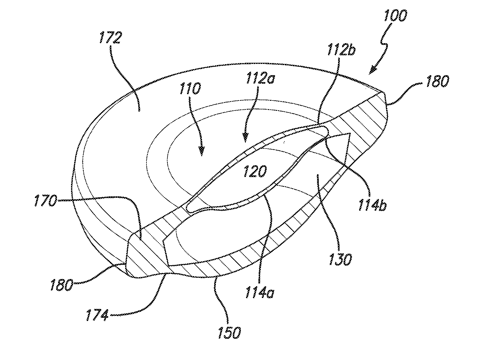
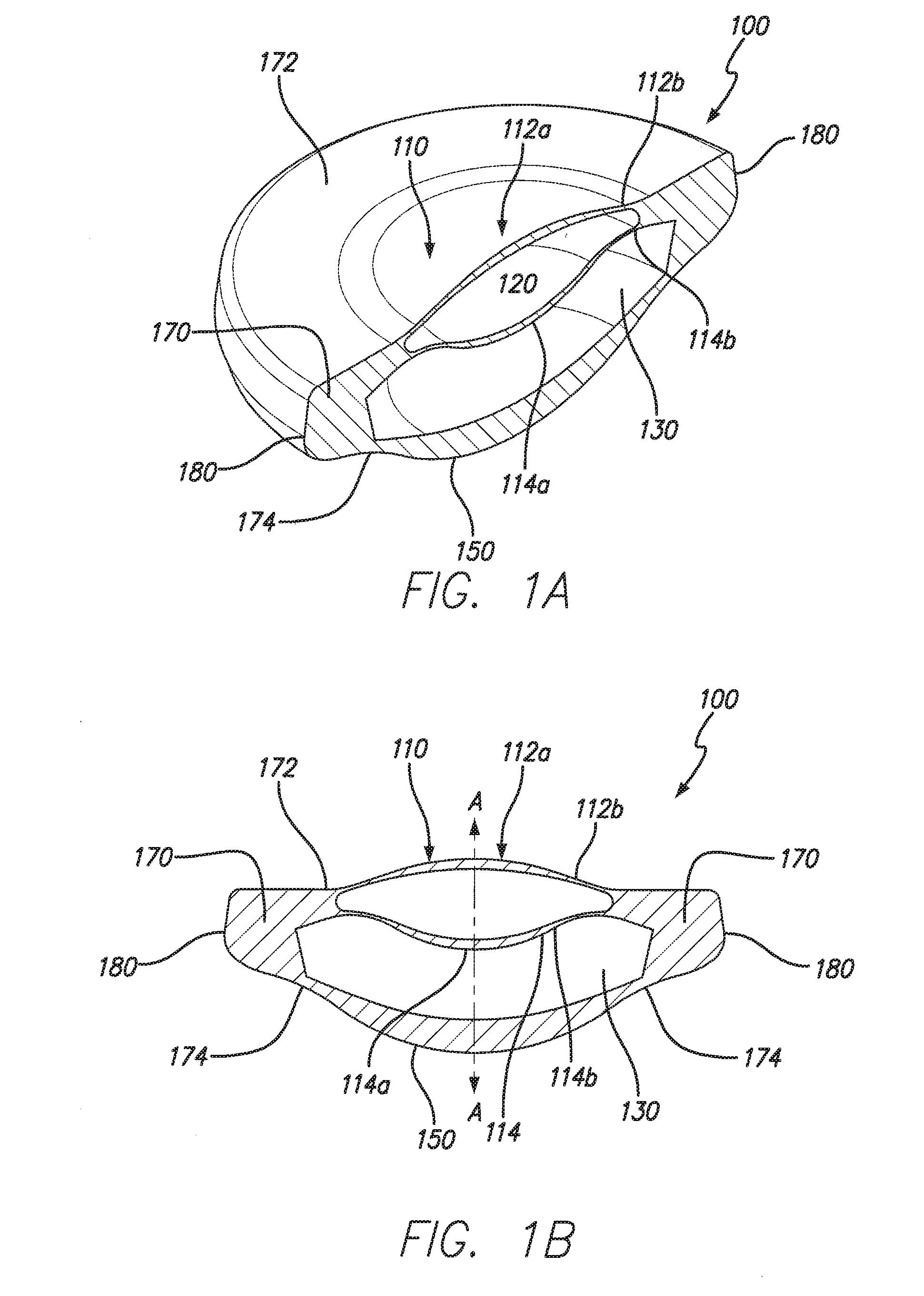
[0054]FIGS. 1A-1B depicts a basic structure of an embodiment of the accommodating intraocular lens (IOL) 100. The IOL 100 is depicted as comprising an elastically deformable lens chamber 110, a base lens 150, and a lens periphery 170 coupling the lens chamber 110 and the base lens 150. The elastically deformable lens chamber 110 provides most, if not all, of the accommodative power by deforming or changing in curvature in response to the radially compressive for...


PUM


Abstract

An intraocular lens (IOL) device comprising a first lens, a second lens and a circumferential haptic. The first lens comprises a pair of opposing and deformable surfaces and a cavity defined therebetween. The first lens has a first lens diameter. The second lens has a second lens diameter. The circumferential haptic has an outer peripheral edge and couples the first lens and the second lens. A main IOL cavity is defined by the circumferential haptic, the first lens and the second lens. The IOL device is resiliently biased to an unaccommodated state, characterized by the IOL device having a first diameter d1 in the absence of radial compressive forces exerted on the outer peripheral edge. The IOL device actuates to an accommodated state being characterized by a second diameter d2 in response to radial compressive forces exerted on the outer peripheral edge, wherein d1>d2.

Description

CROSS-REFERENCE TO RELATED APPLICATIONS[0001]This application is a continuation of International Patent Application No. PCT / US2014 / 063473 filed Oct. 31, 2014, which claims the benefit of Provisional Patent Application No. 61 / 899,106 filed Nov. 1, 2013, both of which are hereby incorporated by reference.FIELD OF THE INVENTION[0002]The invention relates generally to an accommodating intraocular lens device and, more particularly, to an accommodating intraocular lens device configured for implantation in a lens chamber of a subject's eye.BACKGROUND[0003]Surgical procedures on the eye have been on the rise as technological advances permit for sophisticated interventions to address a wide variety of ophthalmic conditions. Patient acceptance has increased over the last twenty years as such procedures have proven to be generally safe and to produce results that significantly improve patient quality of life.[0004]Cataract surgery remains one of the most common surgical procedures, with over...

Claims


Application Information

Patent Timeline
IPC IPC(8): A61F2/16
CPCA61F2/1635A61F2250/0003A61F2002/169A61F2002/1682A61F2/1648A61F2/1601
Inventor SILVESTRINI, THOMASBRADY, DANIELRAO, RAMGOPAL
Owner LENSGEN INC
Why Eureka
Try Eureka