Train brake safety monitoring and fault action system

a technology of fault action and brake safety monitoring, applied in the direction of brake safety systems, vehicle components, braking systems, etc., can solve the problem of unsafe amount of available brake power, and achieve the effect of improving the safety of train braking

Active Publication Date: 2016-11-03
NEW YORK AIR BRAKE CORP
View PDF1 Cites 19 Cited by
  • Summary
  • Abstract
  • Description
  • Claims
  • Application Information

AI Technical Summary

Benefits of technology

[0005]The present invention comprises a train brake safety system for improving train braking safety that includes an actual brake power module programmed to calculate the actual brake power exhibited by a train during operation of the train and a brake efficiency module programmed to determine whether the actual brake power exhibited by the train has fallen below a safe brake power threshold. An expected brake power module may be used to calculate the theoretical brake power of the train. The invention further comprises a response module that initiates one or more actions in response to the actual brake power falling below the safe brake power threshold. Responsive actions may include stopping the train or sending a command to the brake control system to cause a predetermined or proportional increase in the brake pipe set pressure in response to the actual brake power falling below the safe brake power threshold. The safe brake threshold can comprise a percentage of the theoretical expected brake power for the train or the maximum actual brake power of the train as determined by one or more tests performed with the braking system in 100 percent working condition. The safe brake threshold may adjusted according to at least adjustment factor to account for the particular terrain of the route to be traversed by the train, the geographic nature of the route to be traversed, t

Problems solved by technology

If the actual power of the train is less than the expected brake power of the train by a safe brake th

Method used


Image

  • Train brake safety monitoring and fault action system
  • Train brake safety monitoring and fault action system
  • Train brake safety monitoring and fault action system

Examples


Embodiment Construction

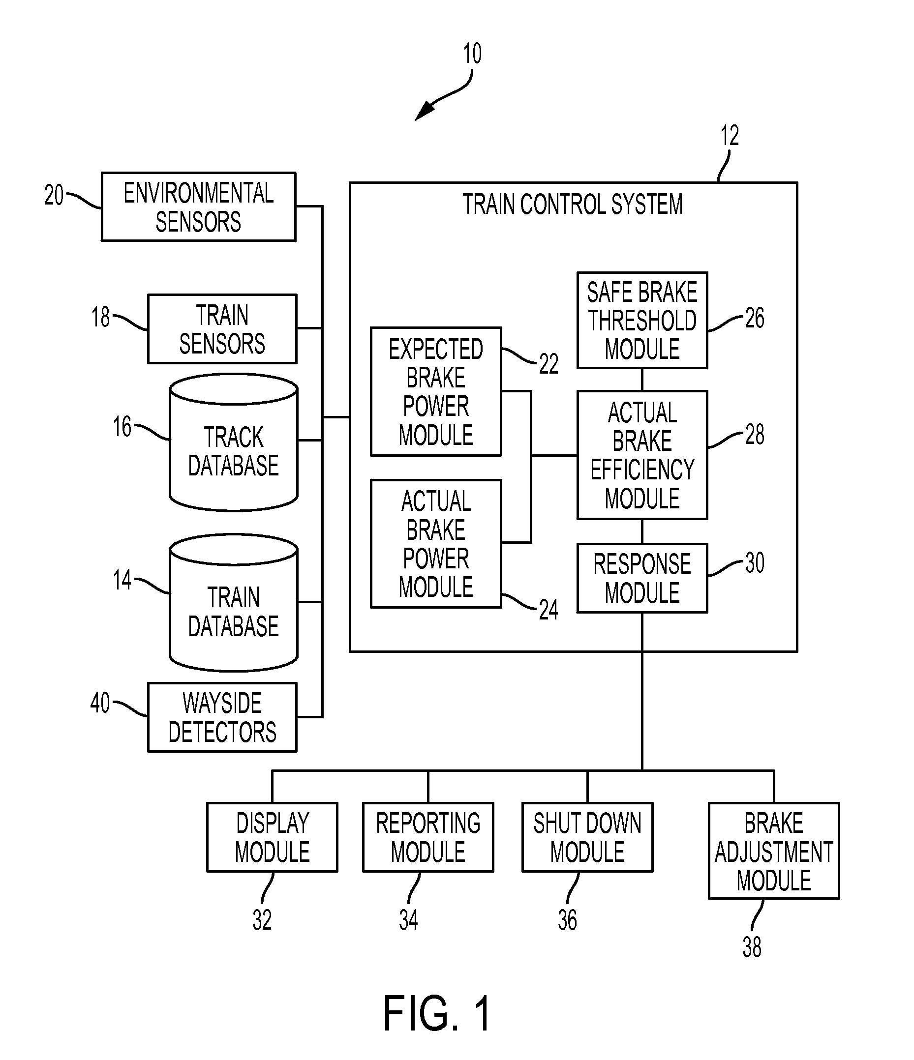
[0011]Referring now to the drawings, wherein like reference numerals refer to like parts throughout, there is seen in FIG. 1 a schematic of a system 10 for providing real-time train brake safety monitoring. System 10 generally comprises a train control system 12, such as such as the LEADER® system available from New York Air Brake LLC of Watertown New York, that is positioned on-board a locomotive of a train and responsible for managing operations of a train. Train control system 12 is further associated with several sources of data about a particular train and the route along which the train with travel, such as a train database 14 having a train manifest that includes information about the nature of weight of all rail cars in the train and the locomotives in the train consist. Train control system 12 is further associated with a track database 16 having a track profile that contains the geographic routes to be taken by the train as well as the specification information about the r...


PUM


Abstract

An on-board train brake safety monitoring and fault action system that compares actual train brake power with expected train brake power to provide real time reporting to the train driver of the margin between the actual brake power and a safe threshold. The system may be configured to automatically make a full service brake penalty if the actual brake system power is less than a safe brake power threshold, such as those required by government regulations, or to adjust the braking system to improve actual brake efficiency. The on-board train brake monitoring system may optionally receive data from wayside hot and cold wheel detector systems to augment the actual brake power measurements.

Description

BACKGROUND OF THE INVENTION[0001]1. Field of the Invention[0002]The present invention relates to train braking systems and, more particularly, to a system for monitoring and addressing the actual power of a train braking system.[0003]2. Description of the Related Art[0004]The braking power of a train is typically the subject of strict government requirements that are designed to ensure the safe operation of trains. In the United States, the Federal Railroad Administration (FRA) has issued complex and burdensome rules governing train braking. For example, the FRA rules require that one hundred percent of the brakes on a train shall be effective and operative brakes prior to use or departure from certain locations. Furthermore, the train shall not move if less than 85 percent of the cars in a train have effective and operative brakes. The failure of the actual braking power of the train to exceed certain thresholds requires the train to be taken out of the service. The FRA rules also ...

Claims


Application Information

Patent Timeline
IPC IPC(8): B60T17/22B60T13/66
CPCB60T13/66B60T17/228B60T13/665
Inventor WRIGHT, ERIC C.CONNELL, JASON
Owner NEW YORK AIR BRAKE CORP
Why Eureka
Try Eureka