Aircraft steering system

Active Publication Date: 2016-11-03
AIRBUS OPERATIONS LTD +1
View PDF1 Cites 6 Cited by
  • Summary
  • Abstract
  • Description
  • Claims
  • Application Information

AI Technical Summary

Benefits of technology

[0022]The controller may be configured to avoid the supply of electrical power generated

Problems solved by technology

This means that there is a relatively high fuel consumption as a result of the poor propulsion efficiency at this low power.
This leads to an increased level of both atmospheric and noise pollution locally around airports.
Moreover, even when the engines are run at low

Method used


Image

  • Aircraft steering system
  • Aircraft steering system
  • Aircraft steering system

Examples


Embodiment Construction

)

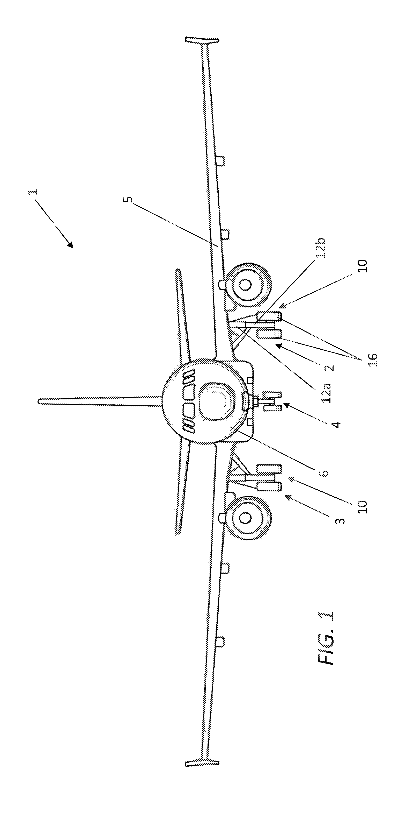
[0036]An embodiment of the invention is shown in FIGS. 1 to 7. As shown in FIG. 1 the aircraft 1 has left and right main landing gear 2, 3 and a nose landing gear 4 (a tricycle configuration). The landing gear each have two wheels (a diablo configuration). The principles of the embodiment may be applied to aircraft with any arrangement of landing gear, and landing gear with any number of wheels, e.g. a single wheel, or four or more wheels.

[0037]Wheel Actuator

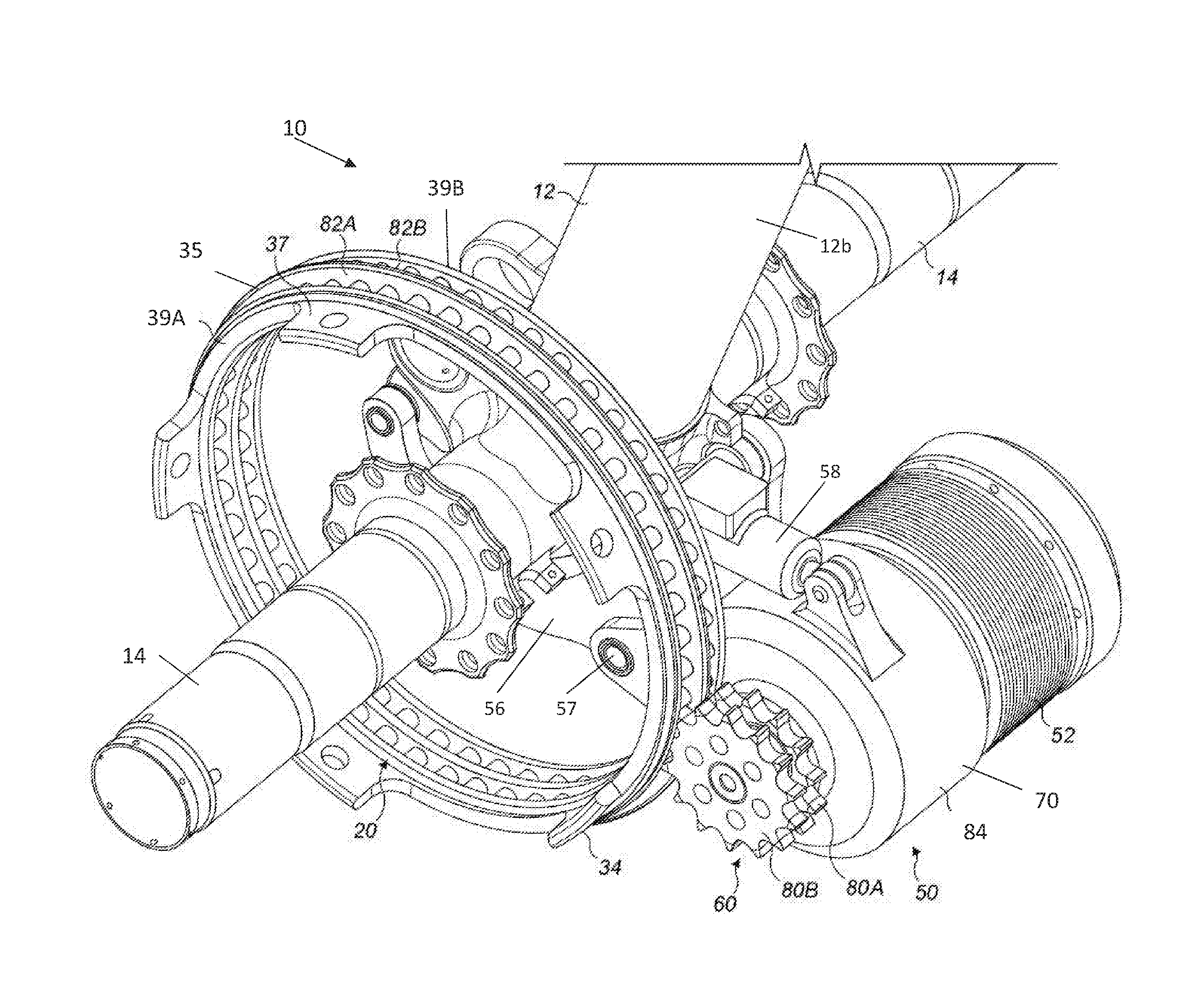
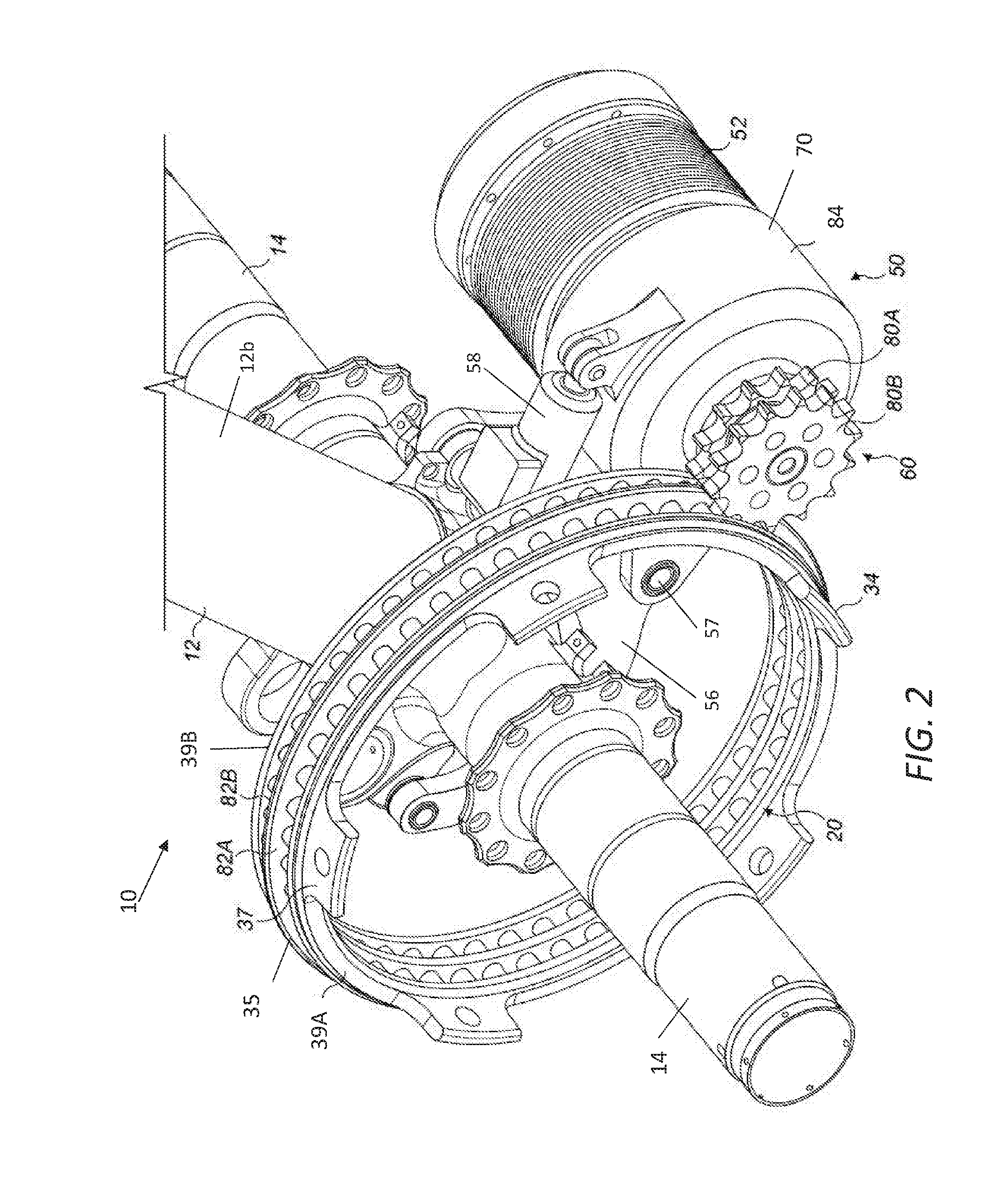
[0038]The landing gear drive system is arranged for driving the main landing gear (i.e. a landing gear attached to wing structure or fuselage structure in the region of the wings), since the weight supported by the main landing gear is considered to provide the best traction between the wheels and the ground to enable reliable aircraft ground taxiing. The main landing gear shown is applicable to a single aisle passenger airliner (approximately 150-200 pax), although it will be appreciated that this invention has wide applicabil...


PUM


Abstract

The invention relates to an aircraft steering system using an aircraft ground taxi drive system whereby electrical power generated by a first motor-generator of a landing gear wheel drive system in a regenerative braking mode is supplied to a second motor-generator of a landing gear wheel drive system in a motorized driving mode.

Description

FIELD OF THE INVENTION[0001]The present invention relates to an aircraft steering system using an autonomous taxiing system.BACKGROUND OF THE INVENTION[0002]Aircraft are required to ground taxi between locations on airfields. An example is taxiing between a runway and the location (e.g. terminal gate) at which the aircraft's passengers are to board or disembark. Typically, such taxiing is achieved by using the thrust from the aircraft's engines to propel the aircraft forwards so that the landing gear wheels are caused to rotate. Since ground taxi speeds are necessarily relatively low, the engines must be run at a very low power. This means that there is a relatively high fuel consumption as a result of the poor propulsion efficiency at this low power. This leads to an increased level of both atmospheric and noise pollution locally around airports. Moreover, even when the engines are run at low power it is generally necessary to apply the wheel brakes to limit ground taxi speeds, lea...

Claims


Application Information

Patent Timeline
IPC IPC(8): B64C25/40B64C25/50B64C25/34
CPCB64C25/405B64C25/50B64C25/34B64C25/36Y02T50/80B64C25/42B64C25/48
Inventor GUERY, XAVIERBRADIER, MATTHIEUMORRIS, JAMES
Owner AIRBUS OPERATIONS LTD
Why Eureka
Try Eureka