
Systems to track a moving sports object

a technology for sports objects and systems, applied in direction finders, image analysis, image enhancement, etc., can solve the problems of difficult detection or measurement of golf balls in camera images, inability to readily obtain accurate data such as positions, speeds or spin rates, and the current camera-based system used to track or trace the trajectories of sports objects suffer from all the known shortcomings of image processing, so as to improve the depth measurement accuracy of camera tracking and improve the accuracy of radar measurements of moving sports objects.

Active Publication Date: 2016-11-03
EDH US
View PDF2 Cites 63 Cited by
  • Summary
  • Abstract
  • Description
  • Claims
  • Application Information

AI Technical Summary

Benefits of technology

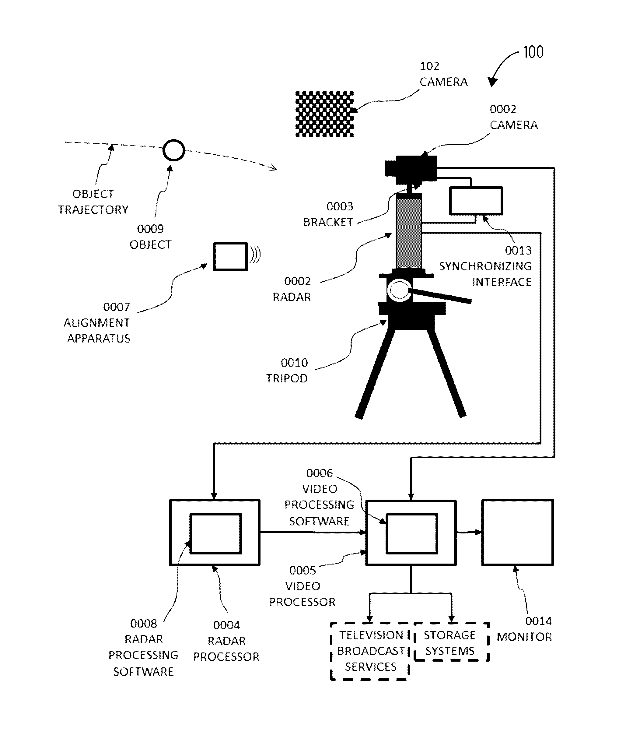
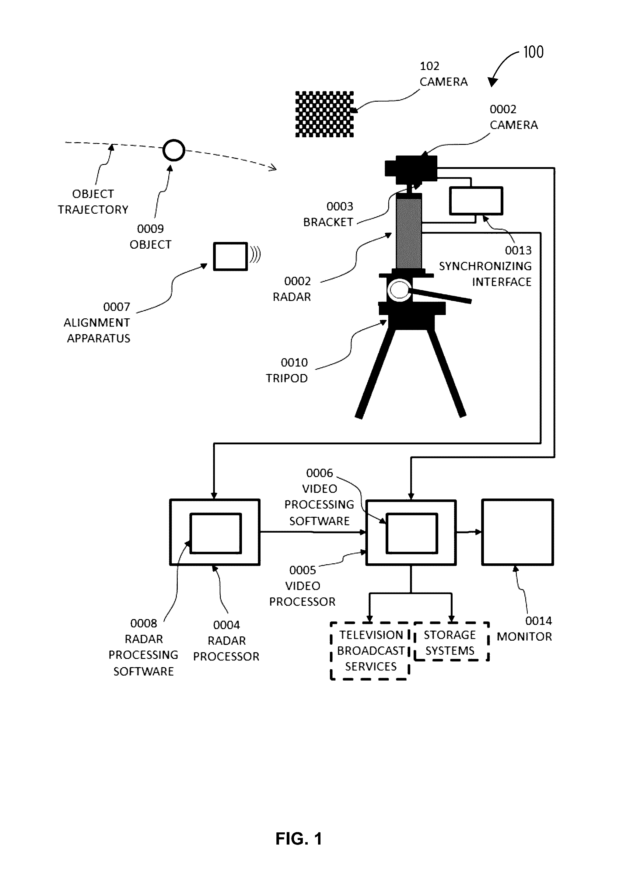
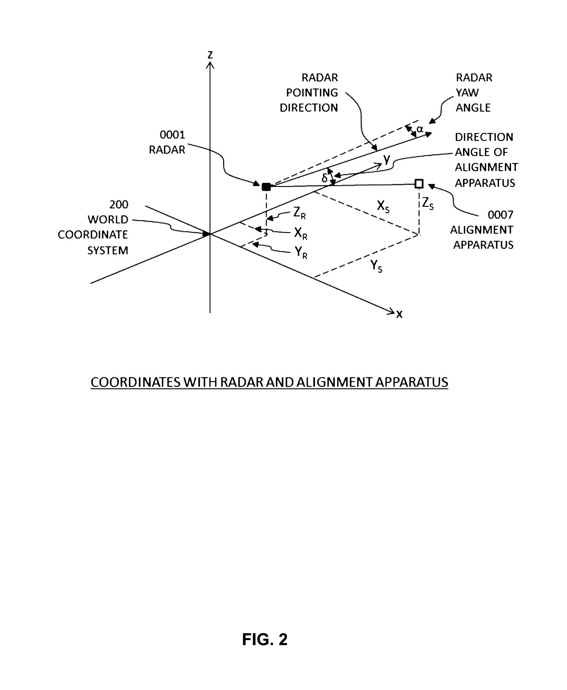
The present patent describes a method for accurately tracking moving sports objects using a combination of camera and Doppler radar. The method improves camera tracking by providing information about the area of interest to the image processing function and extends the achievable tracking distance. It also overcomes temporary or permanent loss of track and improves radar tracking by providing more precise angular and height measurements of the object. The method allows for the generation of a video image to represent the object's instantaneous position or trajectory in the camera's perspective view, which can be mixed with the clean camera feed to animate television feeds with the radar-measured object data. The method can also include calibrating the camera and radar to simultaneously track the object and minimizing differences between the two. Overall, the method provides more accurate and reliable tracking of sports objects.

Problems solved by technology

Current camera based systems used to track or trace the trajectories of sports objects suffer from all the known shortcomings of image processing.
For example a golf ball may be difficult to detect or measure in a camera image due to contrast, ambient light conditions, and camera resolution.
Apart from being able to animate the television images with traces of the ball flight, accurate data such as positions, speeds or spin rates are not readily available from such systems.
Current radar based systems used to track sports objects suffer from other shortcomings unique to radar technology.
For example the vertical angular position or height of an object at low elevation can be severely affected by multipath effects.

Method used


Image

  • Systems to track a moving sports object
  • Systems to track a moving sports object
  • Systems to track a moving sports object

Examples


Embodiment Construction

[0029]“CARRIER SIGNAL” in this context refers to any intangible medium that is capable of storing, encoding, or carrying instructions for execution by the machine, and includes digital or analog communications signals or other intangible medium to facilitate communication of such instructions. Instructions may be transmitted or received over the network using a transmission medium via a network interface device and using any one of a number of well-known transfer protocols.

[0030]“CLIENT DEVICE” in this context refers to any machine that interfaces to a communications network to obtain resources from one or more server systems or other client devices. A client device may be, but is not limited to, a mobile phone, desktop computer, laptop, portable digital assistants (PDAs), smart phones, tablets, ultra-books, netbooks, laptops, multi-processor systems, microprocessor-based or programmable consumer electronics, game consoles, set-top boxes, or any other communication device that a use...


PUM


Abstract

Systems, methods and computer-readable media are provided for tracking a moving sports object. In one example, a method of tracking a moving sports object includes calibrating a perspective of an image of a camera to a perspective of a Doppler radar for simultaneous tracking of the moving sports object, and tracking the moving sports object simultaneously with the camera and Doppler radar. The method may further comprise removing offsets or minimizing differences between simultaneous camera measurements and Doppler radar measurements of the moving sports object. The method may also include combining a camera measurement of an angular position of the moving sports object with a simultaneous Doppler measurement of a radial distance, speed or other measurement of the moving sports object.

Description

CROSS-REFERENCE TO RELATED APPLICATIONS[0001]This application claims the benefit of priority of U.S. Patent Application Ser. No. 62 / 153,574, filed on Apr. 28, 2015, which is herein incorporated by reference in its entirety.BACKGROUND[0002]Current camera based systems used to track or trace the trajectories of sports objects suffer from all the known shortcomings of image processing. For example a golf ball may be difficult to detect or measure in a camera image due to contrast, ambient light conditions, and camera resolution. Current systems that provide traces of ball flight on television feeds or tennis ball trajectories for line calling decisions use image processing techniques to find the ball in successive images and to construct a trace or trajectory from such finds. Apart from being able to animate the television images with traces of the ball flight, accurate data such as positions, speeds or spin rates are not readily available from such systems.[0003]Current radar based sy...

Claims


Application Information

Patent Timeline
IPC IPC(8): G01S13/72G06T7/20G01S13/86
CPCG01S13/72G01S13/867G06T7/2033G06T2207/30221A63B2220/89A63B2220/806A63B2220/16G01S3/7864G01S7/2955G01S7/4026G01S13/58G01S13/726G01S13/88G06T7/20G06T7/80G06T7/246G06T2200/04G06T2207/10016G06T2207/10028G06T7/254G06T7/277
Inventor JOHNSON, HENRI
Owner EDH US
Learn More