Thin telephoto lens and image pickup apparatus including the same

Active Publication Date: 2016-11-10
SAMSUNG ELECTRONICS CO LTD
View PDF1 Cites 35 Cited by
  • Summary
  • Abstract
  • Description
  • Claims
  • Application Information

AI Technical Summary

Benefits of technology

[0055]The image pickup apparatus may be configured to compensate image deterioration of a captured image in a vertical direction based on a difference be

Problems solved by technology

A zoom lens including a refractive optical system is usually long and heavy, and a length of such zoom lens changes while a focal length is adjusted, and thus it is difficult to mount an optical zoom lens in a very thin mobile device such as a mobile phone.
Recently, zoom lenses of various forms that are thin and have a minimized volume have been suggested, but the suggested zoom lenses are not yet compact enough to be used in a mobile

Method used


Image

  • Thin telephoto lens and image pickup apparatus including the same
  • Thin telephoto lens and image pickup apparatus including the same
  • Thin telephoto lens and image pickup apparatus including the same

Examples


exemplary embodiment 1

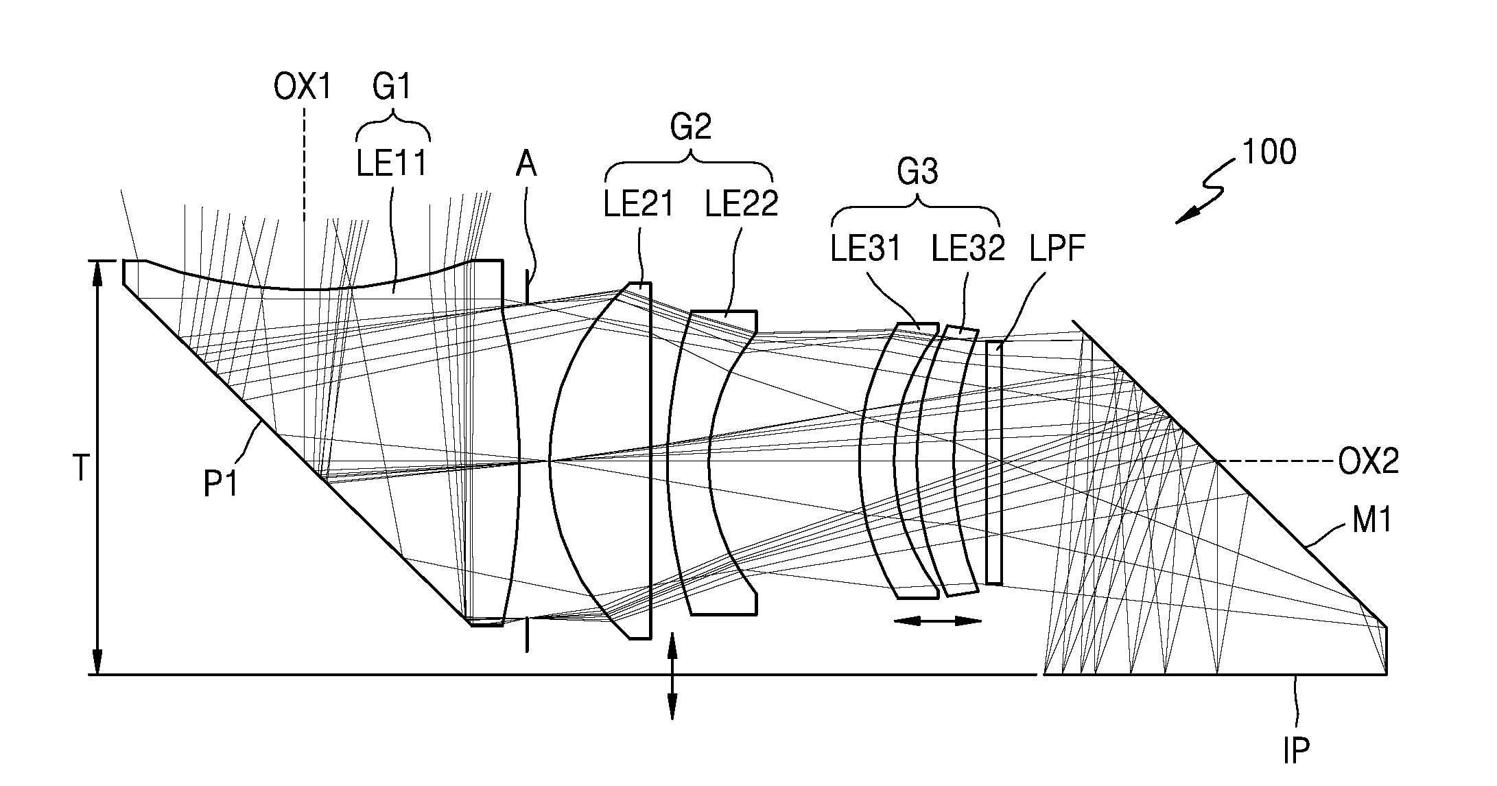
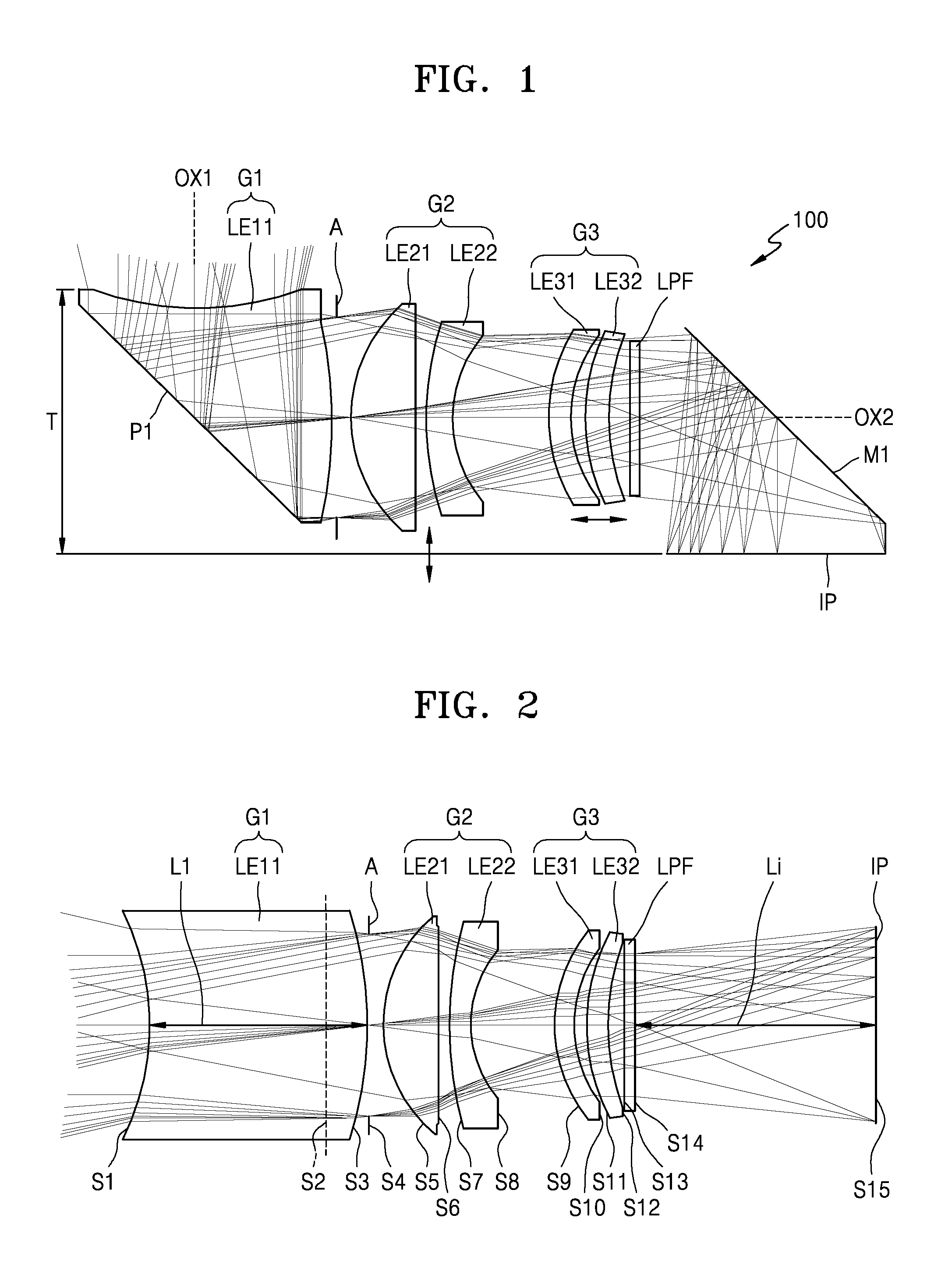
[0090]The thin telephoto lens 100 having the structure illustrated in FIG. 1 is manufactured as Exemplary Embodiment 1. Table 1 below shows detailed optical data of optical elements of the thin telephoto lens 100 according to Exemplary Embodiment 1. In Table 1, a surface ‘0’ denotes an object at an infinite range. In addition, a surface ‘2’ denotes a virtual plane indicating an edge of the prism P1 that is close to the image side lens surface S3 in the first lens element LE11. The other surface numbers shown in Table 1 are identical to lens surface numbers illustrated in FIG. 2.

TABLE 1SurfaceSurfaceTypeRadiusThicknessMaterial0Sphere1.00E+186.31E+13Refract1Asphere−7.582.29531198.5649Refract2Sphere1.00E+184.6531198.5649Refract3Asphere−9.9820.1Refract4Stop1.00E+180.43Refract5Asphere4.321.9101642531198.5649Refract6Asphere−63.7050.3338034Refract7Asphere13.8460.45635500.2389Refract8Asphere4.0462.424819Refract9Asphere4.1730.65635500.2389Refract10Asphere3.7330.4542025Refract11Asphere5.3930....

exemplary embodiment 2

[0095]FIG. 6 is a cross-sectional view of a thin telephoto lens 110 according to an exemplary embodiment, i.e., Exemplary Embodiment 2. According to Exemplary Embodiment 2, in order to manufacture a lens module having a thickness of 6 mm or less and to reduce an effective F-number of the thin telephoto lens 110, an aperture stop A may have a different shape instead of a typical circular shape. For example, as illustrated in FIG. 7A, the aperture stop A may have an oval shape having a size in a Y-axis direction different from a size in an X-axis direction. In this case, in order to reduce a thickness of the thin telephoto lens 110, a vertical diameter d1 of the aperture stop A may be smaller than a horizontal diameter d2 thereof. Alternatively, as illustrated in FIG. 7B, the aperture stop A may have a shape formed by cutting out upper and lower portions of a circle. FIG. 7B illustrates the aperture stop A having a shape formed by cutting both upper and lower portions of a circle. How...

exemplary embodiment 3

[0110]FIG. 14 is a cross-sectional view of a thin telephoto lens 120 according to an exemplary embodiment, i.e., Exemplary Embodiment 3. The thin telephoto lens 120 illustrated in FIG. 14 has a longer focal length than the thin telephoto lens 100 of FIG. 1 or the thin telephoto lens 110 of FIG. 6. As described above, when a focal length of the thin telephoto lens 120 is equivalent to a focal length of about 120 mm or greater in a 35 mm film format, an incidence angle is small and thus it may be advantageous to set a large refraction angle. Accordingly, an object side lens surface S1 of the first lens element LE11 of the first lens group G1 of the thin telephoto lens 120 may be convex.

[0111]Table 5 below shows detailed optical data of optical elements of the thin telephoto lens 120 illustrated in FIG. 14. In Table 5, surfaces ‘2’ and ‘15’ are reflection surfaces of the prism P1 and the mirror M1. The other surface numbers of Table 5 are identical to lens surface numbers illustrated i...


PUM


Abstract

Provided is a telephoto lens including a first lens group, the first lens group including: a first lens element including: an object side lens surface facing an object side; and an image side lens surface facing an image side; and a prism configured to bend an optical path within the first lens element, wherein the first lens element and the prism are formed as a single body, wherein an inclined surface of the prism is provided between the object side lens surface and the image side lens surface, and wherein the following relationship is satisfied: 1.3≦L1/Li, where L1 corresponds to a length of an optical path within the first lens element along an optical axis of the first lens elements and Li corresponds to a length of an optical path between an optical element provided closest to an image plane and the image plane along the optical axis.

Description

CROSS-REFERENCE TO RELATED APPLICATION[0001]This application claims priority from U.S. Provisional Patent Application No. 62 / 158,729, filed on May 8, 2015 in U.S.A. Patent and Trademark Office and Korean Patent Application No. 10-2015-0104354, filed on Jul. 23, 2015, in the Korean Intellectual Property Office, the disclosures of which are incorporated herein by reference in their entireties.BACKGROUND[0002]1. Field[0003]Apparatuses consistent with exemplary embodiments relate to a thin telephoto lens and an image pickup apparatus including the same, and more particularly, to a telephoto lens that is thin enough to be used in a mobile device and an image pickup apparatus including the thin telephoto lens.[0004]2. Description of the Related Art[0005]A zoom lens including a refractive optical system is usually long and heavy, and a length of such zoom lens changes while a focal length is adjusted, and thus it is difficult to mount an optical zoom lens in a very thin mobile device such ...

Claims


Application Information

Patent Timeline
IPC IPC(8): G02B13/00G02B9/60G02B27/64G02B17/08G02B13/02
CPCG02B13/0065G02B17/086G02B9/60G02B27/646G02B13/02
Inventor CHOI, JONG-CHULKHING, HARPAL SINGH
Owner SAMSUNG ELECTRONICS CO LTD
Why Eureka
Try Eureka