Coupling Device for Connecting an Optical Waveguide to an Associated Optical Waveguide Connection

a technology of coupling device and optical waveguide, which is applied in the direction of instruments, catheters, heat measurement, etc., can solve the problems of fiber material melting or even evaporation, substantial risk of optical waveguide overheating, and formation of plasma with temperatures up to 1°C, so as to avoid health risks for patients

Inactive Publication Date: 2016-11-17
INGENERIC +1
View PDF2 Cites 4 Cited by
  • Summary
  • Abstract
  • Description
  • Claims
  • Application Information

AI Technical Summary

Benefits of technology

[0012]The first wavelength range reflected by the optical filter preferably comprises a wavelength range of at least one laser light source outside of the range of visible light, so that only the laser light, but no visible signal radiation, is reflected by the optical filter. The first wavelength range may be within the infrared range beyond 800 nm, whereas the second wavelength range is the wavelength range of visible light, in particular below 800 nm. Thus, the optical filter transmits only the signal radiation in the form of white light that is generated in the event of overheating caused by fiber breakage, whereas the laser light from the laser light source is not transmitted. The transmitted signal radiation is detected by one of the meter means. Upon the detection of signal radiation by one of the meter means, an emergency stop function can be activated that allows a deactivation of the laser light source within a period of a few milliseconds when the waveguide overheats, so that health risks for a patient are avoided.

Problems solved by technology

Especially when used as a catheter in medical technology, there is a substantial risk of an overheating of the optical waveguide.
This heating can cause the fiber material to melt or even evaporate.
Specifically as a result of fiber breakage, the increased laser light absorption, e.g. in the case of a cardiac catheter surrounded by liquid, can lead to the formation of plasma with temperatures up to 1,000° C. Especially with cardiac catheters patients run a 50% risk of death due to the plasma formed in the event of overheating.

Method used


Image

  • Coupling Device for Connecting an Optical Waveguide to an Associated Optical Waveguide Connection
  • Coupling Device for Connecting an Optical Waveguide to an Associated Optical Waveguide Connection
  • Coupling Device for Connecting an Optical Waveguide to an Associated Optical Waveguide Connection

Examples


Embodiment Construction

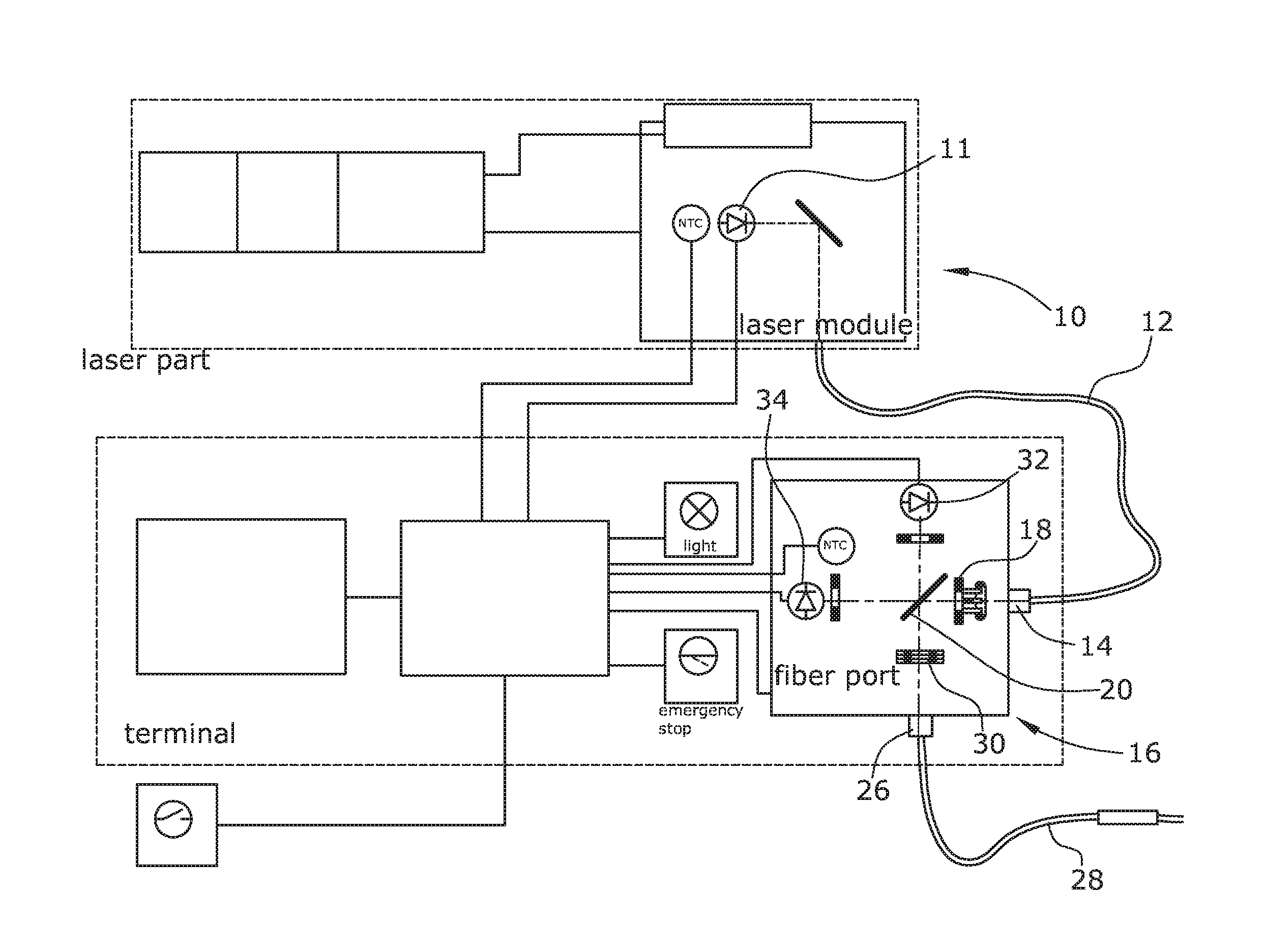
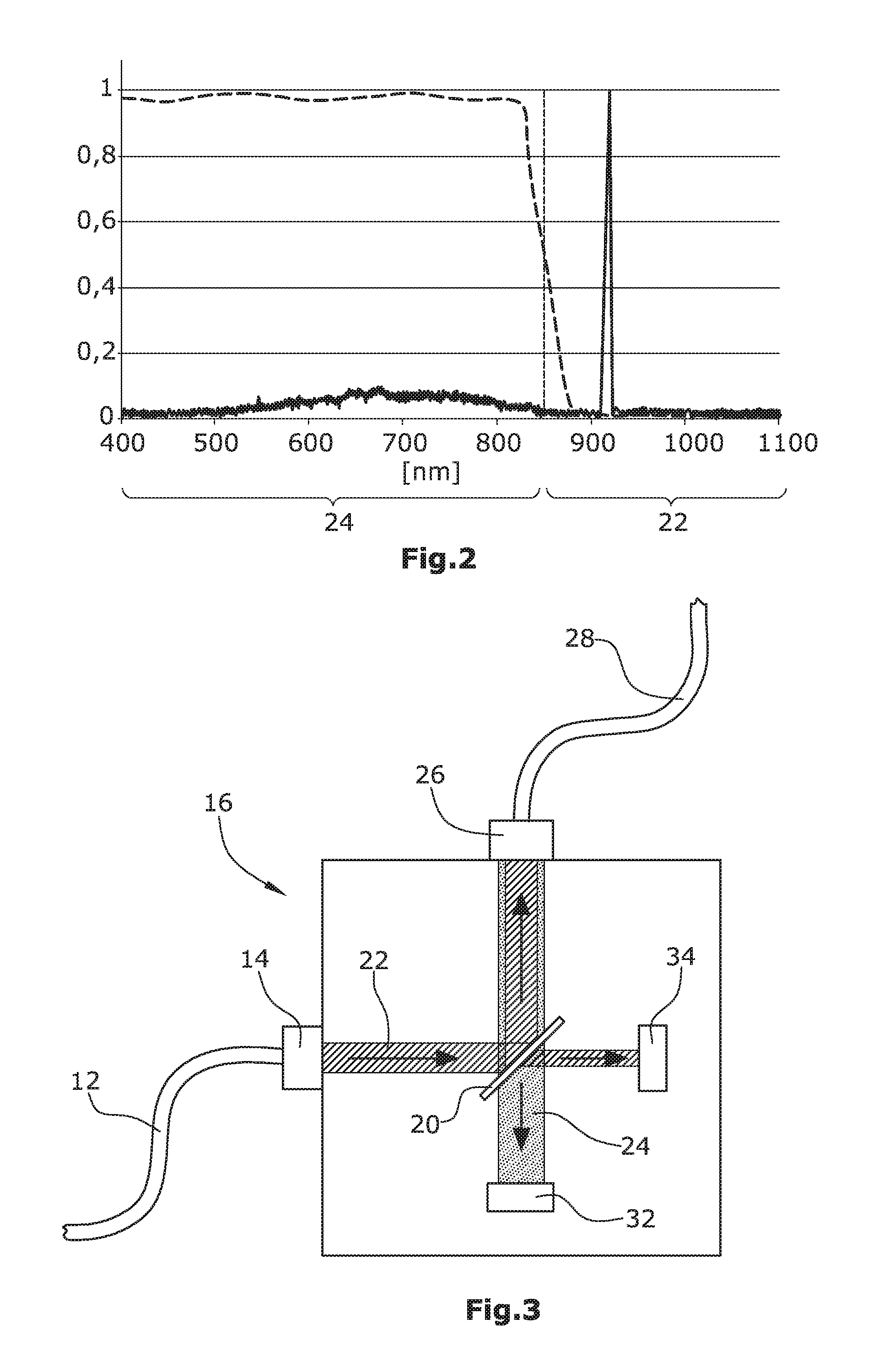
[0025]FIG. 1 illustrates a laser device 10 of conventional design comprising a laser light source 11 in the form of a laser diode for generating laser light. The laser light has a working wavelength of about 980 nm that is outside the wavelength range of visible light of 380-780 nm. The laser light generated is coupled into a second optical waveguide 12 and is coupled into the coupling device 16 of the invention via the waveguide inlet 14. The laser light coupled in is directed onto the optical filter 20 through bundling optics 18, which filter is arranged in the beam path from the waveguide inlet 14 to the optical filter 20 under an inclination of about 45° relative to the propagation of the laser light.

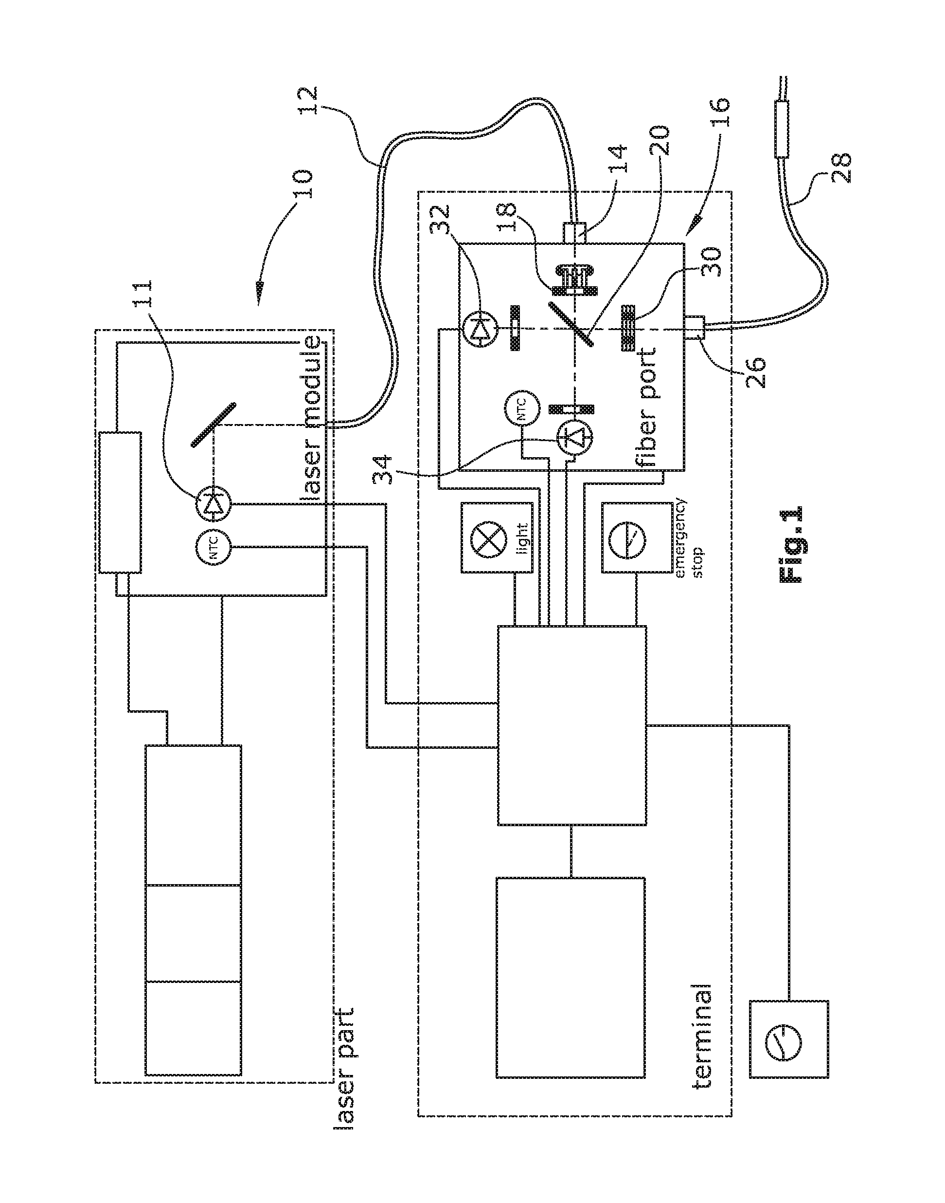
[0026]The optical filter 20 reflects light in a first wavelength range 22 of more than 850 nm, whereas light of the second wavelength range 24, which is less than 850 nm, is transmitted. Thus, the laser light coupled in, having a wavelength of 980 nm, is reflected by the optical fil...


PUM

PropertyMeasurementUnit
temperaturesaaaaaaaaaa
angleaaaaaaaaaa
wavelength rangeaaaaaaaaaa

Abstract

A coupling device for an optical waveguide includes an optical waveguide connection for a first optical waveguide. The coupling device includes an optical filter arranged in a beam path between a laser light source and the optical waveguide connection which reflects light of a first wavelength range or a first polarization direction and transmits light of a second wavelength range or a second polarization direction.

Description

CROSS-REFERENCE TO RELATED APPLICATIONS[0001]This application is a continuation of U.S. patent application Ser. No. 14 / 117,974, which is the United States national phase of International Application No. PCT / EP2012 / 056683 filed Apr. 12, 2012, which claims priority to German Patent Application No. 10 2011 102 079.2, filed May 19, 2011, the disclosures of which are hereby incorporated by reference in their entirety.BACKGROUND OF THE INVENTION[0002]1. Field of the Invention[0003]The invention refers to a coupling device for connecting an optical waveguide to the associated optical waveguide connection.[0004]2. Description of Related Art[0005]A coupling device couples the light generated by a laser light source into an optical waveguide for further use. The optical waveguide may be a part of a catheter or a medical product, for example, intended to introduce the laser light into the body of a human being or an animal for therapeutic or diagnostic purposes. As an alternative, the optical ...

Claims


Application Information

Patent Timeline
Patent Type & Authority Applications(United States)
IPC IPC(8): G01K11/12A61B18/24G02B6/26
CPCG01K11/12G02B6/262A61B2018/00172A61B2018/00351A61B2090/049A61B18/24A61B2018/2255A61B90/04A61B2018/20361A61B2018/2247G02B6/29361G02B6/3845G02B6/27G02B6/293G02B6/42
Inventor KALLENDRUSCH, JANSINHOFF, VOLKERWESSLING, CHRISTIANMARKUS, KAI ULF
Owner INGENERIC
Why Eureka
Try Eureka