Localisation system

Active Publication Date: 2016-11-17
TELEVIC HEALTHCARE
View PDF6 Cites 0 Cited by
  • Summary
  • Abstract
  • Description
  • Claims
  • Application Information

AI Technical Summary

Benefits of technology

[0029]This installation methodology takes full advantage of the features of the present invention to keep the length of the address field in

Problems solved by technology

It is a disadvantage of the known system that the processing that must be carried out at the identification tags is relatively complex, and tha

Method used


Image

  • Localisation system
  • Localisation system
  • Localisation system

Examples


Embodiment Construction

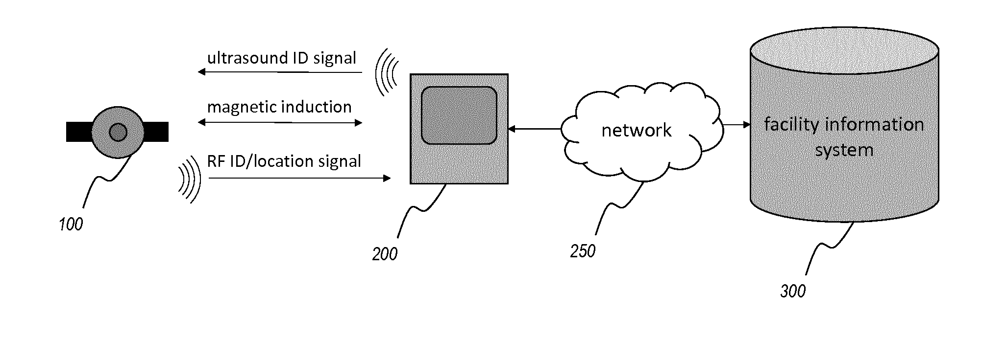
[0035]FIG. 1 schematically illustrates a location system comprising beacons and tags according to an embodiment of the present invention.

[0036]A specific application of the location system described herein is a wireless nurse call system for use in hospitals and other institutions where patients may move about, possibly without being fully conscious of their own exact location. Where appropriate, the invention will be described with reference to such a nurse call system, without intent to limit the scope of the invention to such applications. In the context of a wireless nurse call system, the development of efficient hardware and efficient communication protocols is an important goal, with a view to reducing (battery) power consumption, obtaining a small form factor, and keeping the total cost as low as possible.

[0037]In the preferred localisation system, beacons 200 are provided at fixed locations throughout an area in which the location of mobile objects or persons is to be monit...


PUM


Abstract

The invention pertains to a method and system for determining a location of an identification tag (100) in a monitored area. The method comprises using a plurality of beacons (200) to broadcast (2010) beacon messages comprising an identification element relating to the originating beacon; receiving (2020) at a first set of beacons a localisation message from an identification tag (100), the tag having received (1010) a beacon message, extracted (1020) the identification element from the received beacon message, and transmitted (1030) information related to the identification element as part of the localisation message; performing (3010) a first level of localisation of the tag on the basis of characteristics of the respective copies of the localisation message received at the first set of beacons; and performing (3020) a second level of localisation of the tag on the basis of the information related to the identification element.

Description

FIELD OF THE INVENTION[0001]The present invention relates to a wireless localisation system for movable objects or persons, such as a system to track the location of patients and / or assets in a facility such as a hospital, and corresponding methods.BACKGROUND[0002]WO 2004 / 051303 A1 discloses a method and a system for monitoring and position determination of objects and / or living beings within an area, such as, e.g. a room in a building or a road tunnel. The system comprises a plurality of identification tags equipped with an ultrasonic receiver and radio transmitter which is attached to the objects that have to be monitored. The identification tags receive ultrasonic signals whose arrival time they measure. This information together with the identification tags' ID code are transmitted by radio waves to a central unit which calculates the position of each of the identification tags.[0003]It is a disadvantage of the known system that the processing that must be carried out at the ide...

Claims


Application Information

Patent Timeline
IPC IPC(8): G01S5/02G01S1/02G01S1/72
CPCG01S5/0263G01S1/02G01S1/72G01S5/0252G01S5/0236G01V15/00G01S13/74G06Q10/06G01S5/183
Inventor CROMBEZ, PIETERGESQUIERE, JOHN
Owner TELEVIC HEALTHCARE
Why Eureka
Try Eureka