
Quantum rod film

a technology of rods and films, applied in the field ofquantum rod films, can solve the problems of increased luminance, insufficient light intensity, and insufficient brightness of display screens

Active Publication Date: 2016-11-17
BENQ MATERIALS CORP
View PDF4 Cites 7 Cited by
  • Summary
  • Abstract
  • Description
  • Claims
  • Application Information

AI Technical Summary

Benefits of technology

The present invention provides a quantum rod film with a unique structure that allows for improved and efficient light emission. The quantum rod film includes a first barrier layer, a sub-wavelength microstructure, and a reflective layer. The quantum rods are aligned in a direction perpendicular to the gratings in the sub-wavelength microstructure, and the major axes of the quantum rods are aligned in a direction perpendicular to the gratings. The quantum rod film also has improved optical properties, such as high brightness and durability, which make it useful in various applications such as display screens and lighting devices.

Problems solved by technology

In another example, concentrating the light of large viewing angle area of the liquid crystal display can increase the luminance at viewing direction, However, those solutions may increase the luminance of the backlight unit of a liquid crystal display: no significant effect is provided to the gamut and the color saturation of the liquid crystal display.
Thus, when the light generated from the backlight module with a quantum rod film passes through the polarizers of the liquid crystal display, the brightness of the display is not as expected.
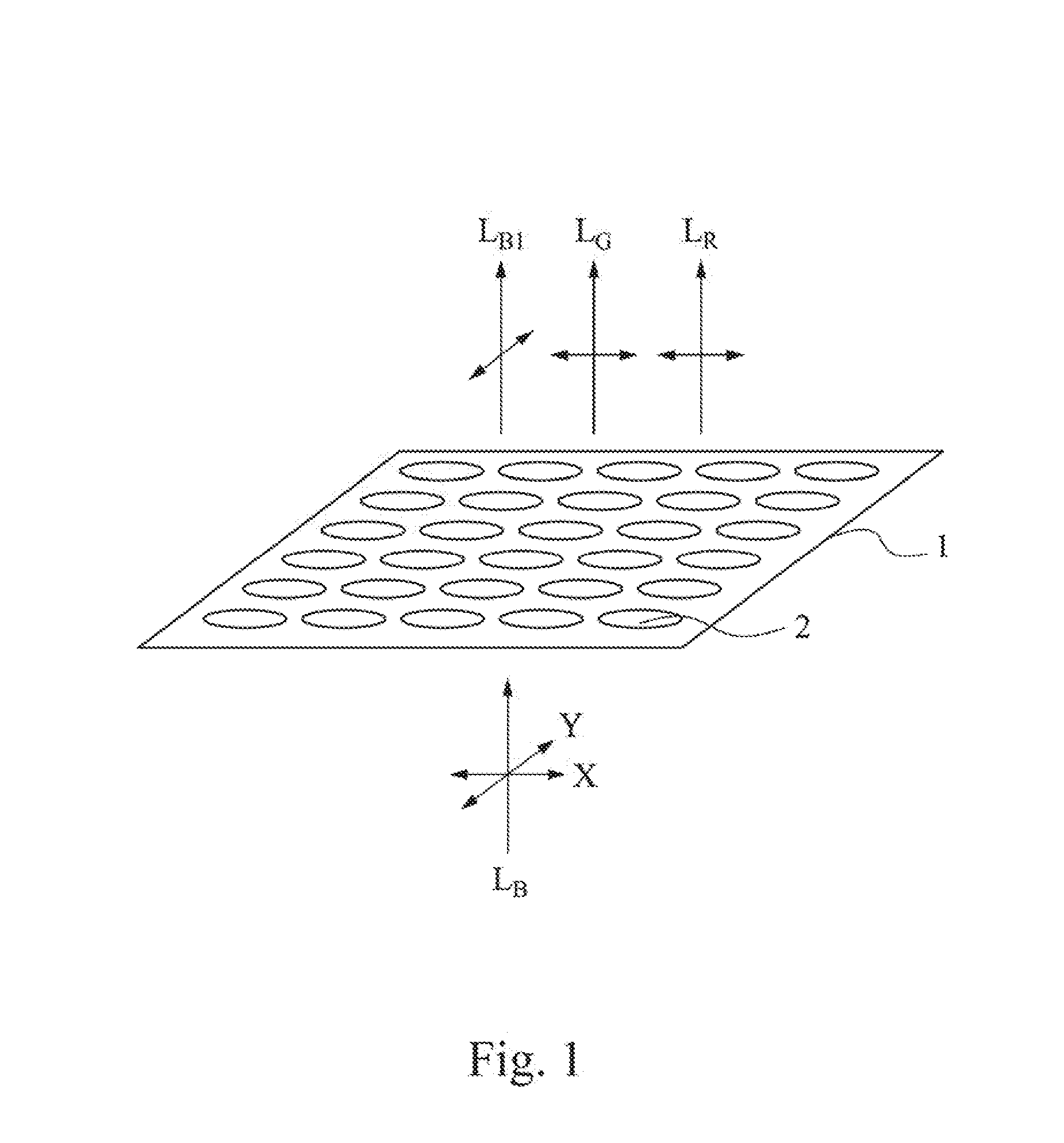
Furthermore, if most of the blue light backlight source (LB) directly passes through the quantum rods 2, the red light (LR) and green light (LG) are emitted less, and the light intensity will be insufficient.
The cost of the quantum rod film will increase.

Method used


Image

  • Quantum rod film
  • Quantum rod film
  • Quantum rod film

Examples


Embodiment Construction

[0026]The invention can be more fully understood by reading the following detailed description of the embodiment, with reference made to the accompanying drawings that illustrate the invention and it should be noted that the drawings are not to scale and only for illustration only.

[0027]The quantum rod film of the present invention will now be described in reference to the accompanying drawings. Similar numbers on the drawings refers to the same elements.

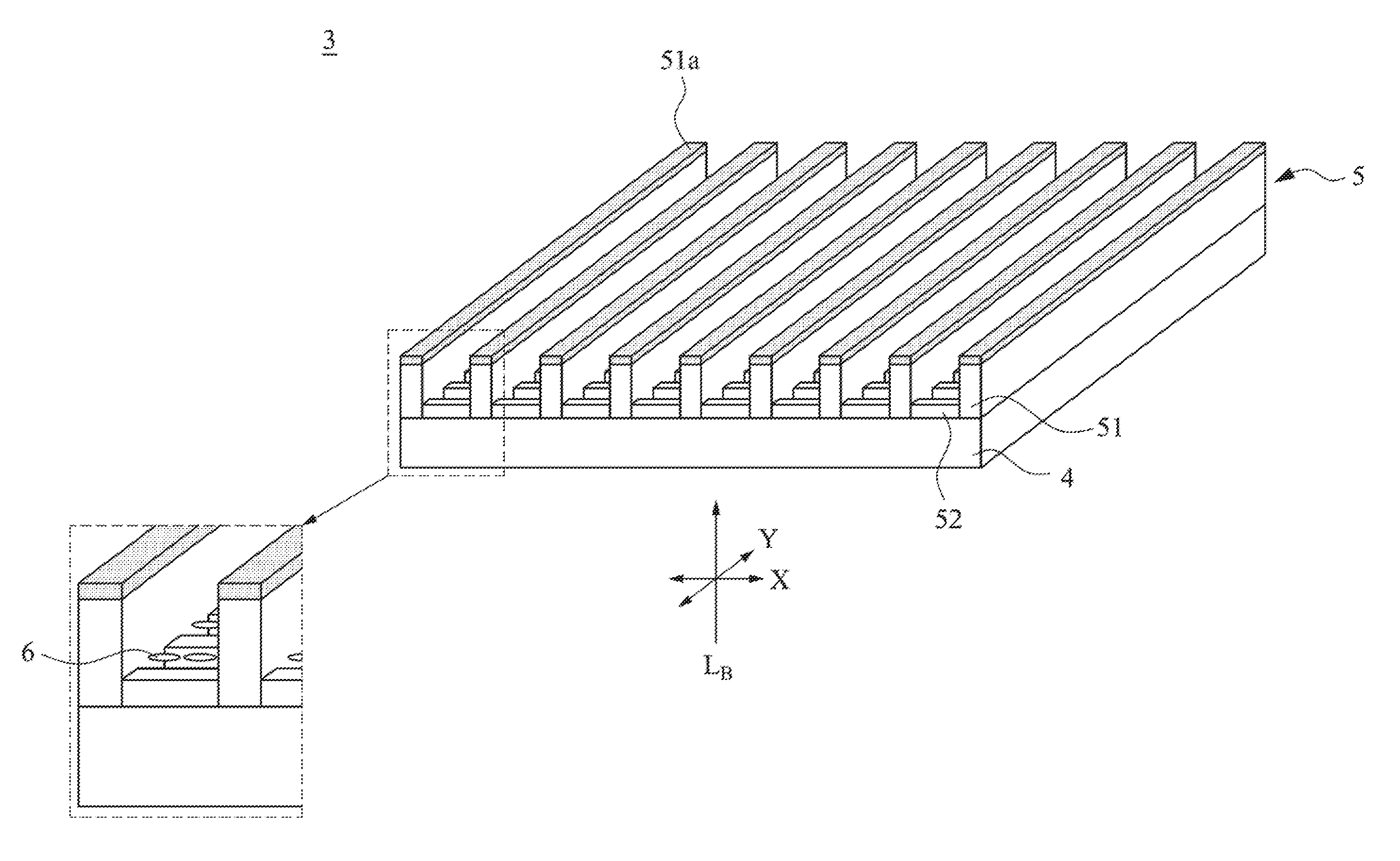
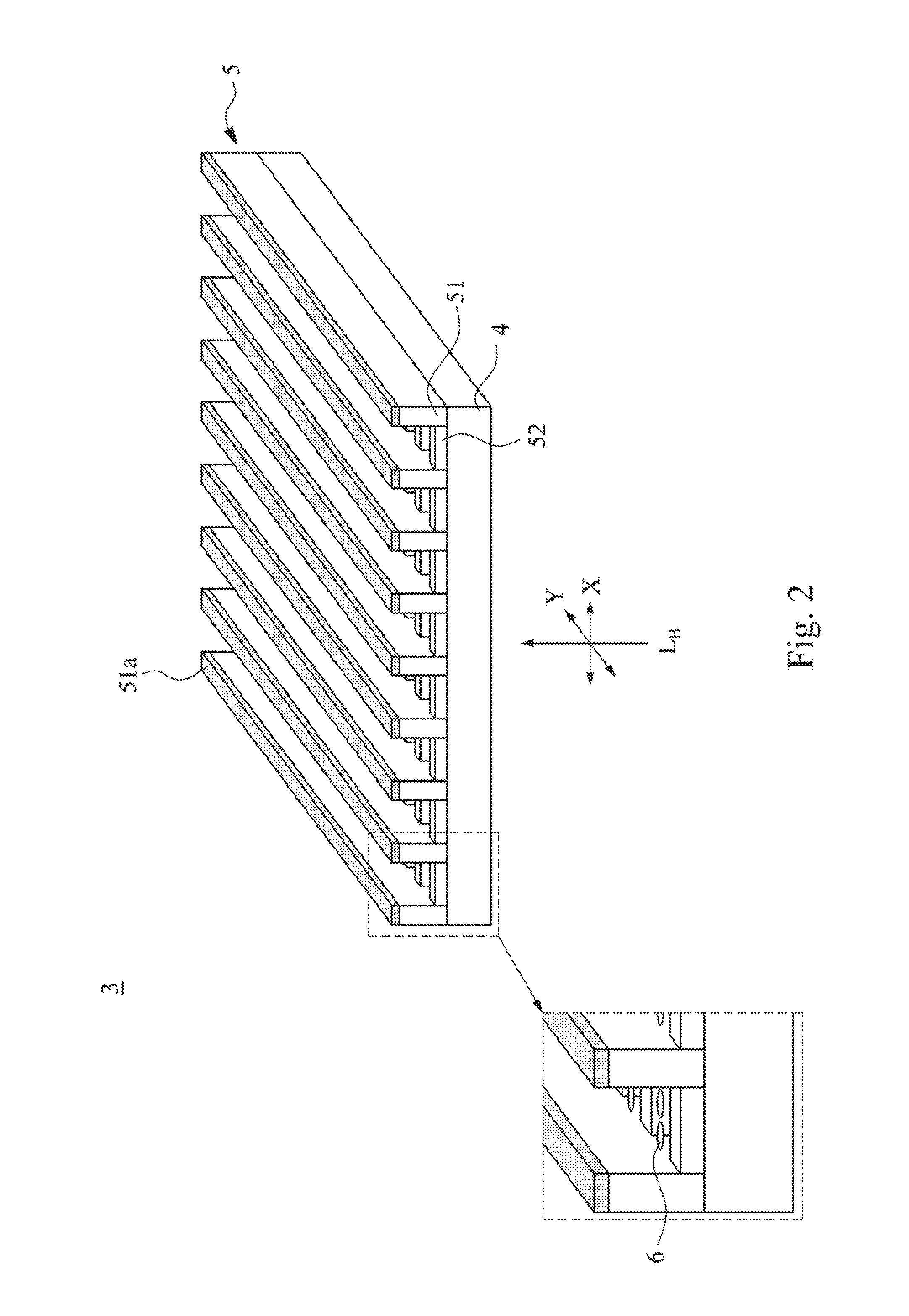
[0028]Now referring to FIG. 2, it is a perspective view of a quantum rod film 3 of a preferred embodiment of the present invention. In a preferred embodiment of the present invention, the quantum rod film 3 includes a first barrier layer 4 disposed at a side receiving light incident from the backlight source (LB); a sub-wavelength microstructure 5 disposed on the first barrier layer 4, wherein the sub-wavelength microstructure 5 including gratings 51 aligned in a parallel direction, an alignment microstructure 52 disposed in grooves...


PUM


Abstract

A quantum rod film for a backlight unit of a liquid crystal display is disclosed herein. The quantum rod includes a first barrier layer, a sub-wavelength microstructure on the first barrier layer, and a plurality of quantum rods, wherein the sub-wavelength microstructure includes gratings aligned n a parallel direction an alignment microstructure disposed in grooves between the gratings in a direction perpendicular to the gratings, and a reflective layer on upper surfaces of the gratings. A plurality of quantum rods are arranged in the alignment microstructure of the sub-wavelength microstructure, and major axes of the quantum rods are aligned in a direction perpendicular to the gratings.

Description

RELATED APPLICATIONS[0001]This application claims priority to Taiwanese Application Serial Number 104115271, filed May 13, 2015, which is herein incorporated by reference.BACKGROUND[0002]1. Field of Invention[0003]This invention generally relates to a quantum rod film used in backlight unit of liquid crystal display for enhancing the gamut and light utilization of the liquid crystal display.[0004]2. Description of Related Art[0005]Polarizers commonly used in the liquid crystal display are absorptive polarizers. in the liquid crystal display, when the non-polarized light emitted from the backlight is incident onto the absorptive polarizers, a component of the incident light parallel to the absorption axis direction of the polarizers is absorbed and cannot pass through the absorptive polarizers. Therefore, after the light emitted from backlight passing through the absorptive polarizer, the light will lose at least 50%. In addition, after the light further passing through the electrode...

Claims


Application Information

Patent Timeline
IPC IPC(8): G02B5/20G02B5/18F21V7/05
CPCG02B5/207G02B5/1819G02B5/1809F21V7/05G02F1/133609G02F1/13362G02F2201/30G02F2202/36G02F1/133614H01L33/60
Inventor WU, JIAN-HUNGCHAO, SHIH-WEI
Owner BENQ MATERIALS CORP
Learn More