Quantum rod light-emitting display device

a display device and light-emitting technology, applied in semiconductor devices, light demodulation, instruments, etc., can solve the problems of difficult to reduce fabrication cost, low optical transmission efficiency of lcd b>1/b>, power consumption, etc., to maximize the efficiency of light emitted, low power consumption, and high transmittance

Active Publication Date: 2014-12-02
LG DISPLAY CO LTD
View PDF19 Cites 6 Cited by
  • Summary
  • Abstract
  • Description
  • Claims
  • Application Information

AI Technical Summary

Benefits of technology

[0017]An object of the embodiments of the invention is to provide a display device that may be configured more simply than a conventional liquid crystal display (LCD) and exhibit low power consumption and high transmittance.
[0018]Another object of the embodiments of the invention is to provide a display device capable of maximizing efficiency of light emitted by a backlight unit (BLU).

Problems solved by technology

Thus, the LCD 1 has very low optical transmission efficiency.
To increase the luminance of the light emitted by the BLU 20, power consumption should increase, and a large number of components are required during a fabrication process, thereby making it difficult to reduce fabrication cost.
In particular, a blue emission material has a relatively short lifetime, which is shorter than the lifespan of a typical display device.

Method used


Image

  • Quantum rod light-emitting display device
  • Quantum rod light-emitting display device
  • Quantum rod light-emitting display device

Examples


Embodiment Construction

[0030]Reference will now be made in detail to embodiments of the invention, examples of which are illustrated in the accompanying drawings.

[0031]To begin with, a quantum rod used in embodiments of the invention will be briefly described.

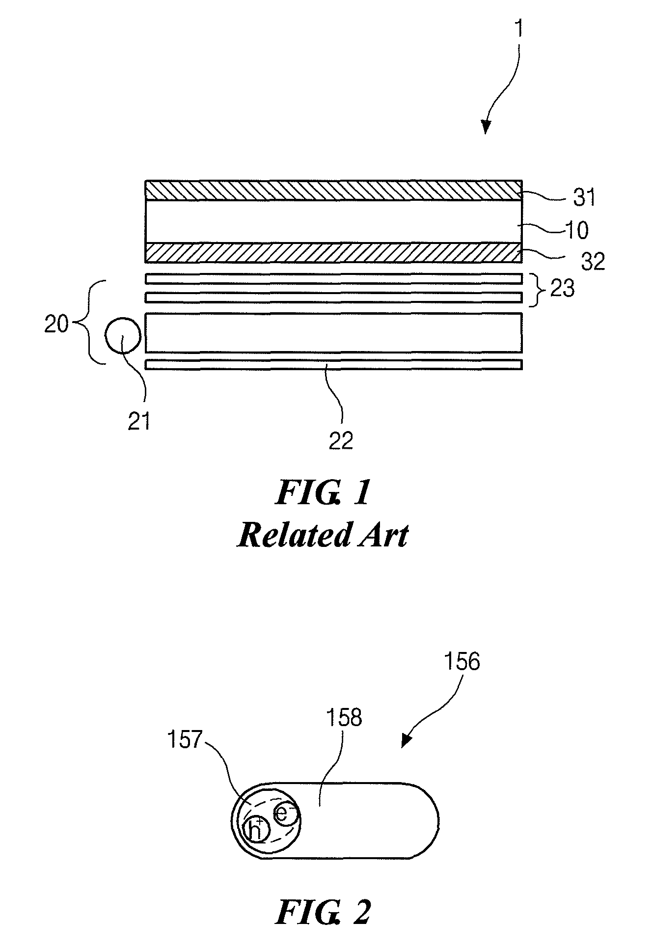
[0032]FIG. 2 illustrates a quantum rod according to an embodiment of the invention.

[0033]As shown in FIG. 2, a quantum rod 156 includes a core 157 forming a center portion of the quantum rod 156 and a shell 158 surrounding the core 157.

[0034]In an example embodiment of the invention, although the quantum rod 156 of FIG. 2 includes the core 157 and the shell 158 surrounding the core 157, the shell 158 may be omitted and the quantum rod 156 may include only the core 157.

[0035]Although FIG. 2 illustrates that the core 157 of the quantum rod 156 has a spherical shape, the core 157 may have any one of a spherical shape, an elliptical spherical shape, a polyhedral shape, and a rod shape. Other shapes may be used for the core 157. When the quantum rod 156 i...


PUM


Abstract

A quantum rod light-emitting display device according to an embodiment of the invention includes a display panel including a first substrate, a second substrate opposite to the first substrate, and a quantum rod layer disposed between the first substrate and the second substrate, wherein quantum rods in the quantum rod layer are arranged in one direction; a backlight unit provided under the display panel and configured to provide light to the display panel; and a short-wavelength pass filter film formed between the display panel and the backlight unit, and configured to transmit the light having a predetermined wavelength range.

Description

CROSS-REFERENCE TO RELATED APPLICATION[0001]This application claims priority to and the benefit of Korean Patent Application No. 10-2012-0068586 filed in Republic of Korea on Jun. 26, 2012, the disclosure of which is hereby incorporated by reference in its entirety.BACKGROUND OF THE INVENTION[0002]1. Field of the Invention[0003]Embodiments of the invention relate to a quantum rod light-emitting display device, and more particularly, to a quantum rod light-emitting display device capable of maximizing optical efficiency using a display panel including a quantum rod layer.[0004]2. Discussion of the Related Art[0005]In recent years, highly efficient flat panel displays (FPDs), which may be made ultrathin and lightweight, and which consumes less power, have been required in various fields.[0006]Among these, a liquid crystal display (LCD) has been most widely used as a typical FPD.[0007]As shown in FIG. 1, which is a schematic cross-sectional view of a typical LCD, an LCD 1 may include a...

Claims


Application Information

Patent Timeline
Patent Type & Authority Patents(United States)
IPC IPC(8): H01L29/00
CPCG02F2203/62G02F1/174G02F2201/086G02F1/0105G02F1/1368G02F2203/34G02F2203/30G02F2203/05G02F2202/36G02F2/02H01L33/04
Inventor JEON, ILKIM, KYUNG-CHANPARK, JOONG-PILLGEE, MOON-BAECHO, SUNG-HEEJANG, KYUNG-KOOKJEONG, KYUNG-SEOK
Owner LG DISPLAY CO LTD
Why Eureka
Try Eureka