
Polarizer

a polarizer and light technology, applied in the field of polarizers, can solve the problems of reducing the durability, heat fading of the quantum rod to reduce the fluorescent efficiency, and the polarization efficiency of the polarized light of the backlight is still insufficien

Active Publication Date: 2016-09-01
BENQ MATERIALS CORP
View PDF5 Cites 7 Cited by
  • Summary
  • Abstract
  • Description
  • Claims
  • Application Information

AI Technical Summary

Benefits of technology

The present invention provides a new polarizer that includes a polarizing layer and a quantum rod layer. The quantum rod layer enhances the brightness of the polarizer and allows for the polarizing layer to transmit strong, polarized light. This new polarizer can be used without increasing the thickness of the backlight unit or liquid crystal display, and is not affected by heat generated from the light source. This solves the problems of previous polarizers in the art.

Problems solved by technology

However, the semiconductor material of the quantum rods is susceptible to be adversely affected by oxygen and moisture in ambient environment to result in decreased durability thereof.
Furthermore, because the quantum rod layer is disposed in the backlight unit and is close to the light source, the heat generated from the light source will cause the heat fading of the quantum rods to decrease the fluorescent efficiency thereof, if no heat dissipation or insulation device is provided to the quantum rod layer.
In case of that a single quantum rod film is arranged with a backlight to be a polarized light source without any other optical films, such as a variety of optical functional films or polarizer, the polarization efficiency of the polarized light of backlight is still insufficient.

Method used


Image

  • Polarizer
  • Polarizer
  • Polarizer

Examples


Embodiment Construction

[0021]The polarizers disclosed in the present invention are set forth in the appended claims. Objectives, advantages, and a preferred mode of making and using the polarizers may be understood best by reference to the following detailed description in conjunction with the accompanying drawings. The description provides information that enables a person skilled in the art to make and use the claimed subject matter, but may omit certain details already well-known in the art. The following detailed description is, therefore, not to be taken in a limiting sense, and the scope of the illustrative embodiments are defined only by the appended claims.

[0022]The polarizers of the present invention will now be described in reference to the accompanying drawings. Similar numbers on the drawings refers to the same elements.

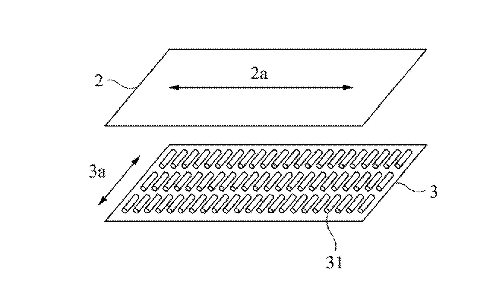
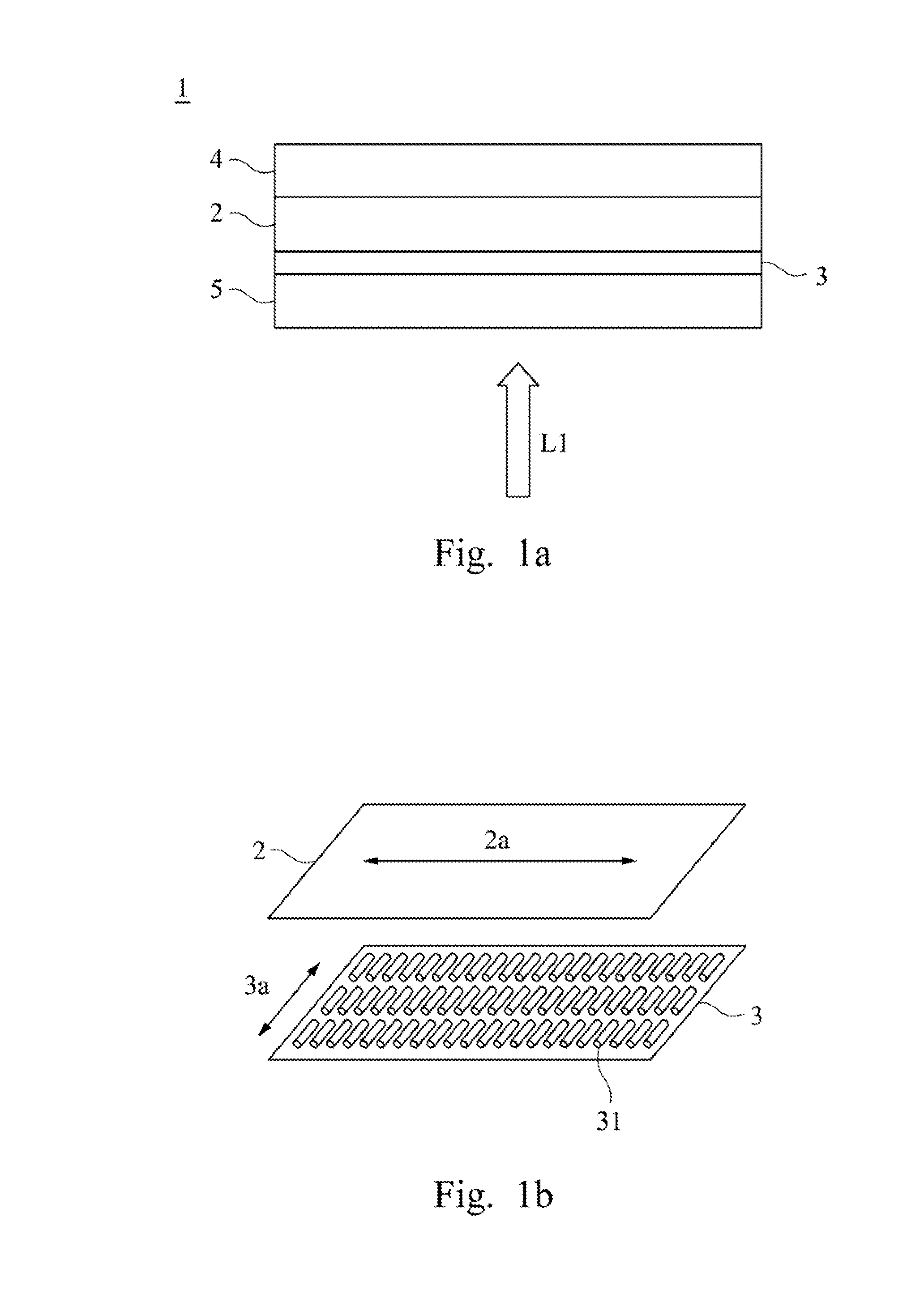
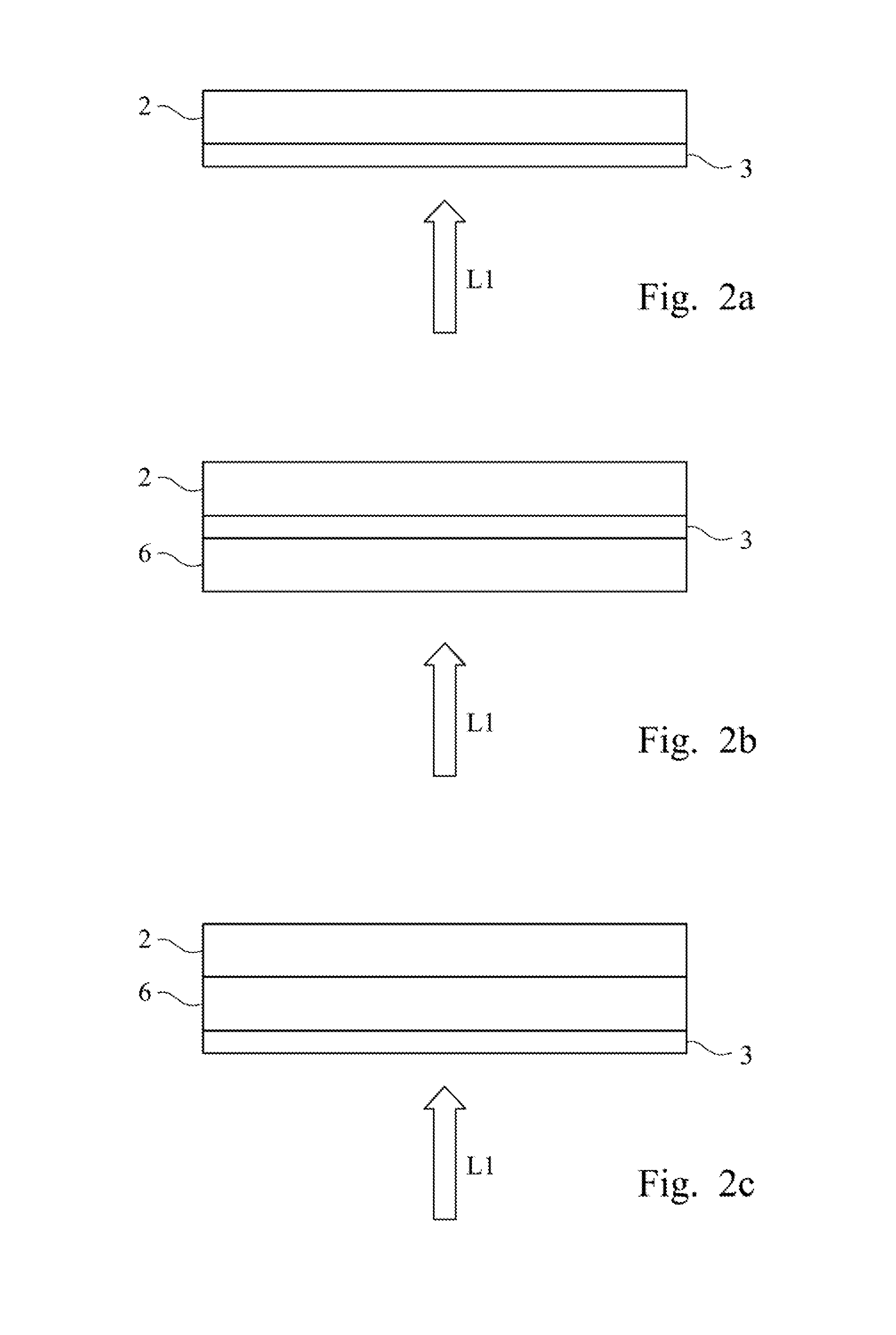
[0023]FIGS. 1a and 1b show the perspective views of the polarizer 1 of a preferred exemplary embodiment of the present invention. The polarizer 1 includes a polarizing layer 2 ...


PUM


Abstract

Disclosed herein is a polarizer for LCD. The polarizer includes a polarizing layer, a quantum rods layer comprising a plurality of quantum rods, a first protective layer and a second protective layer, wherein major axis of the quantum rods is aligned in a direction perpendicular to the absorption axis of the polarizing layer. Accordingly, the incident unpolarized light emitted from the backlight unit can be transferred to be polarized light by the quantum rods layer and pass through the polarizing layer directly for enhancing the utility of the backlight.

Description

RELATED APPLICATIONS[0001]This application claims the priority benefit of Taiwanese application serial no. 104106271, filed on Feb. 26, 2015, which is incorporated herein by reference.FIELD OF THE INVENTION[0002]This invention relates to a polarizer used in a liquid crystal display. Particularly, the invention relates to an integral polarizer containing a quantum rod layer for enhancing color gamut and light utilization of the liquid crystal display.BACKGROUND OF THE INVENTION[0003]Polarizers commonly used in the liquid crystal display are absorptive polarizers. When, in a liquid crystal display, the non-polarized light emitted from the backlight is incident onto the absorptive polarizers, the incident light with a direction parallelly to the absorption axis direction of the polarizers is absorbed and not transmitted. Therefore, light emitted from backlight after passing through an absorptive polarizer will lose at least 50%. In addition, the light after passing through the polarize...

Claims


Application Information

Patent Timeline
IPC IPC(8): G02B1/14G02B5/30
CPCG02B5/3025G02B1/14G02B5/30G02F1/133528G02F1/133617G02F2202/36G02B5/3058G02F1/133531
Inventor KUO, CHEN-KUANCHAO, SHIH-WEIHUANG, REN-HUNG
Owner BENQ MATERIALS CORP
Learn More