
Cyclonic separator

a technology of cyclonic separator and separator plate, which is applied in the direction of vortex flow apparatus, membranes, separation processes, etc., can solve problems such as degrading separation efficiency

Inactive Publication Date: 2016-11-24
AIRBUS OPERATIONS LTD
View PDF3 Cites 10 Cited by
  • Summary
  • Abstract
  • Description
  • Claims
  • Application Information

AI Technical Summary

Benefits of technology

The patent describes a system for removing water from fuel tank to prevent problems associated with water condensation within the tank, even at low temperatures. The system includes a cyclonic separator that separates water from the fuel and optionally burns it off. The purified fuel is then fed back into the fuel tank to keep the concentration of water low. The system also includes an inner wall that prevents water from being entailed back into the bulk fluid and enables a smaller diameter of the outer wall. Additionally, the system controls the concentration of water fed to the engine so it does not exceed the recommended limit by the engine manufacturers.

Problems solved by technology

A problem with such a known cyclonic separator is that although the overall cyclonic action spins the water out to the separator wall, the fluid dynamic may shear the water off the wall and entrain it back into the bulk fluid due to turbulence, degrading the efficiency of separation.

Method used


Image

  • Cyclonic separator
  • Cyclonic separator
  • Cyclonic separator

Examples


Embodiment Construction

)

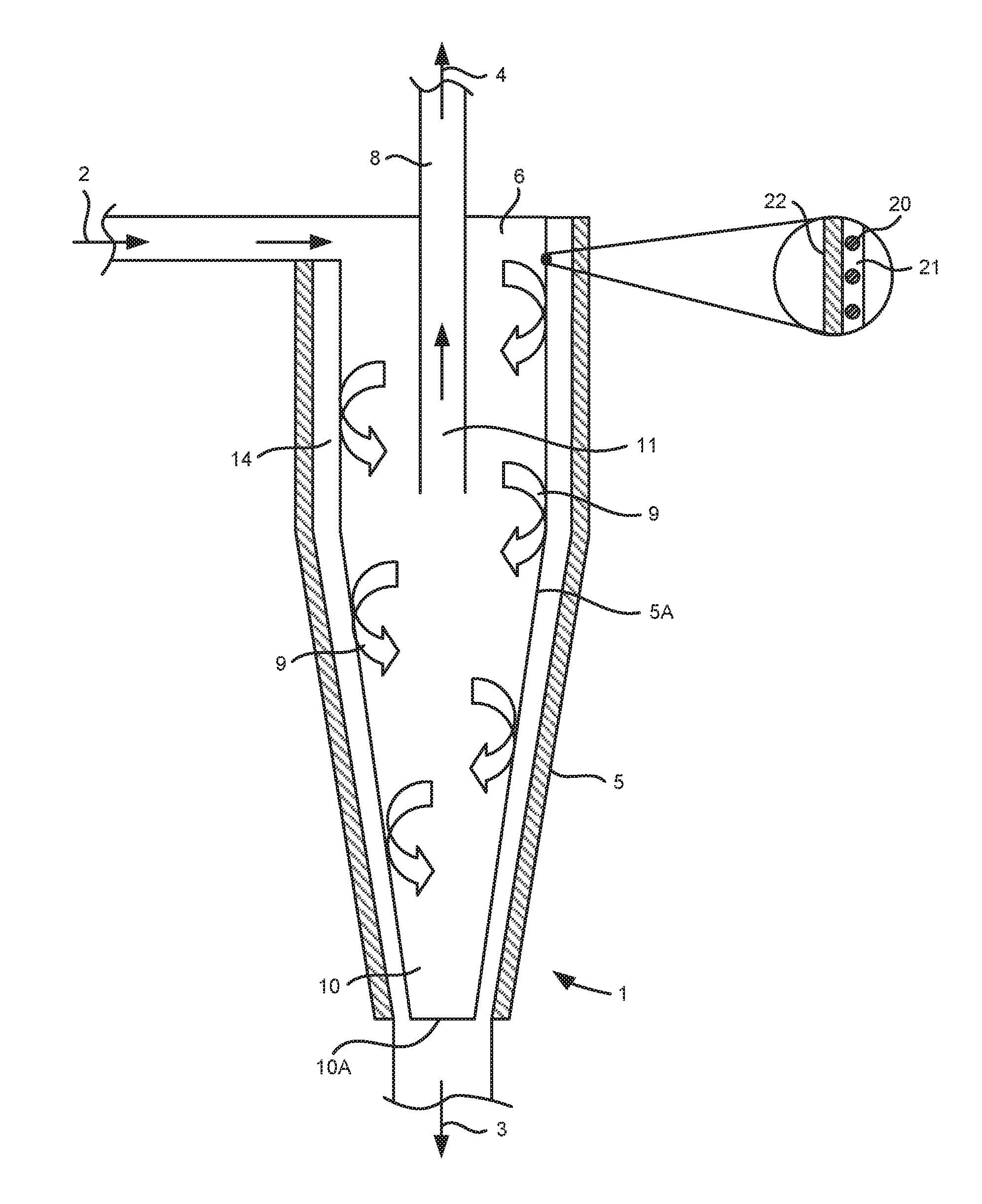
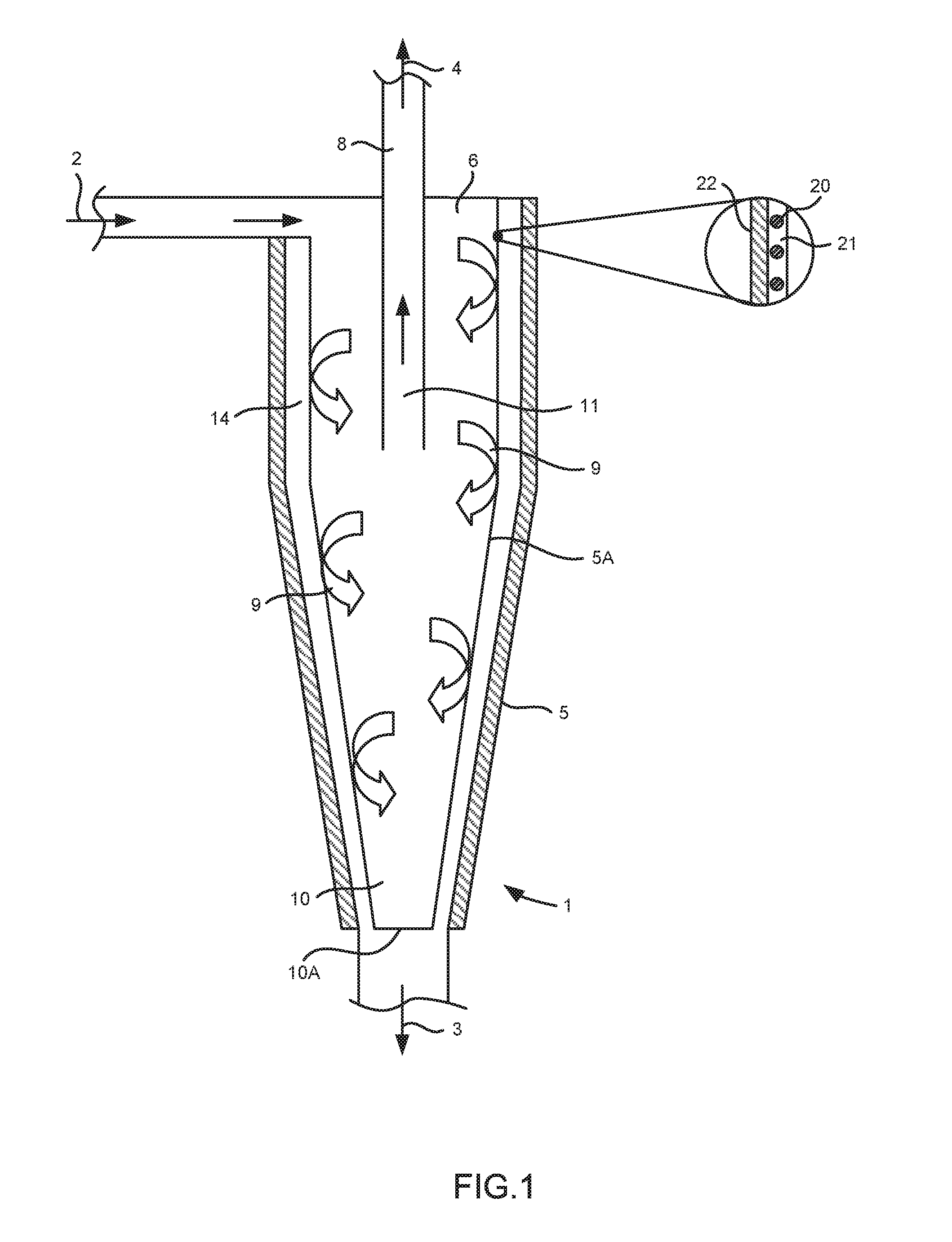
[0042]FIG. 1 illustrates schematically a cyclonic separator 1 having an inlet 2, a water outlet 3 and a fuel outlet 4. The cyclonic separator 1 has a cylindrical upper portion and a conical lower portion. The conical lower portion has a conical outer wall 5 having a downwardly narrowing, frusto-conical shape that symmetrically extends around a centrally disposed, longitudinal axis. An upper end 6 of the cyclonic separator 1 has a larger diameter and is disposed above a lower end 7 of the cyclonic separator 1 having a smaller diameter. The inlet 2 is disposed adjacent the upper end 6 and the water outlet 3 is disposed adjacent the lower end 7. A pipe 8 extends into the upper portion of the cyclonic separator 1 and is fluidically connected to the fuel outlet 4.

[0043]FIG. 2a illustrates schematically a top view of the cyclonic separator 1 to show the arrangement of the inlet 2 to the upper end 6 of the cyclonic separator 1. FIG. 2b illustrates the three-dimensional flow within the cyc...


PUM


Abstract

A cyclonic separator with an inlet, a fuel outlet, an inner wall comprising a water-permeable material, an outer wall, a cavity between the inner wall and the outer wall, and a water outlet. The cyclonic separator is adapted to discharge water from the water outlet via the cavity and relatively less dense liquid fuel from the fuel outlet. The water-permeable material enables water in the cyclonic separator to flow through the water-permeable material into the cavity, but substantially prevents liquid fuel in the cyclonic separator from doing so.

Description

FIELD OF THE INVENTION[0001]The present invention relates to a cyclonic separator, and a fuel system including a cyclonic separator.BACKGROUND OF THE INVENTION[0002]A known cyclonic separator is described in US 2012 / 0000864. The cyclonic separator has an inlet fluidically connected to a fuel tank, a water outlet fluidically connected to an engine fuel feed system, and a fuel outlet. The cyclonic separator is adapted to discharge relatively denser material (including water) from the water outlet and relatively less dense material from the fuel outlet.[0003]A problem with such a known cyclonic separator is that although the overall cyclonic action spins the water out to the separator wall, the fluid dynamic may shear the water off the wall and entrain it back into the bulk fluid due to turbulence, degrading the efficiency of separation.[0004]“Unimpeded Permeation of Water Through Helium-Leak-Tight Graphene-Based Membranes”, R. R Nair et al, Science, 27 Jan. 2012, Vol. 335, no. 6067, p...

Claims


Application Information

Patent Timeline
Patent Type & Authority Applications(United States)
IPC IPC(8): B04C9/00F02C7/22B04C5/08
CPCB04C9/00B04C2009/004F02C7/22B04C5/08B01D17/02B01D17/0217B01D17/045B64D37/005C10G33/06C10G2300/208B04C5/10B01D17/085B64D37/34B01D2311/2676
Inventor LAM, JOSEPH K-WLISLE-TAYLOR, STEPHEN
Owner AIRBUS OPERATIONS LTD
Learn More