Electric motor and electric pump

Inactive Publication Date: 2016-11-24
JOHNSON ELECTRIC INTERNATIONAL AG
View PDF67 Cites 20 Cited by
  • Summary
  • Abstract
  • Description
  • Claims
  • Application Information

AI Technical Summary

Benefits of technology

[0004]Hence there is a desire for an elec

Problems solved by technology

However, these electric motors have a comparativel

Method used


Image

  • Electric motor and electric pump
  • Electric motor and electric pump
  • Electric motor and electric pump

Examples


Embodiment Construction

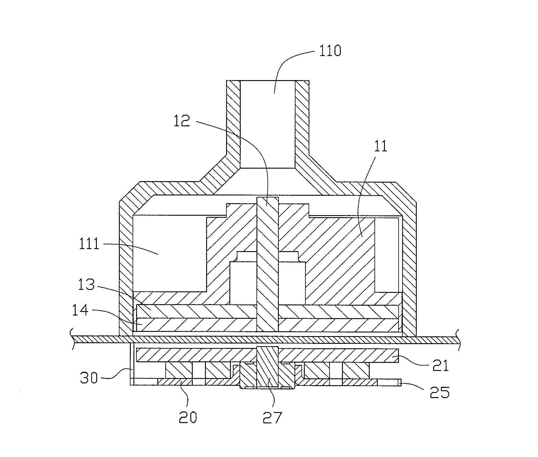
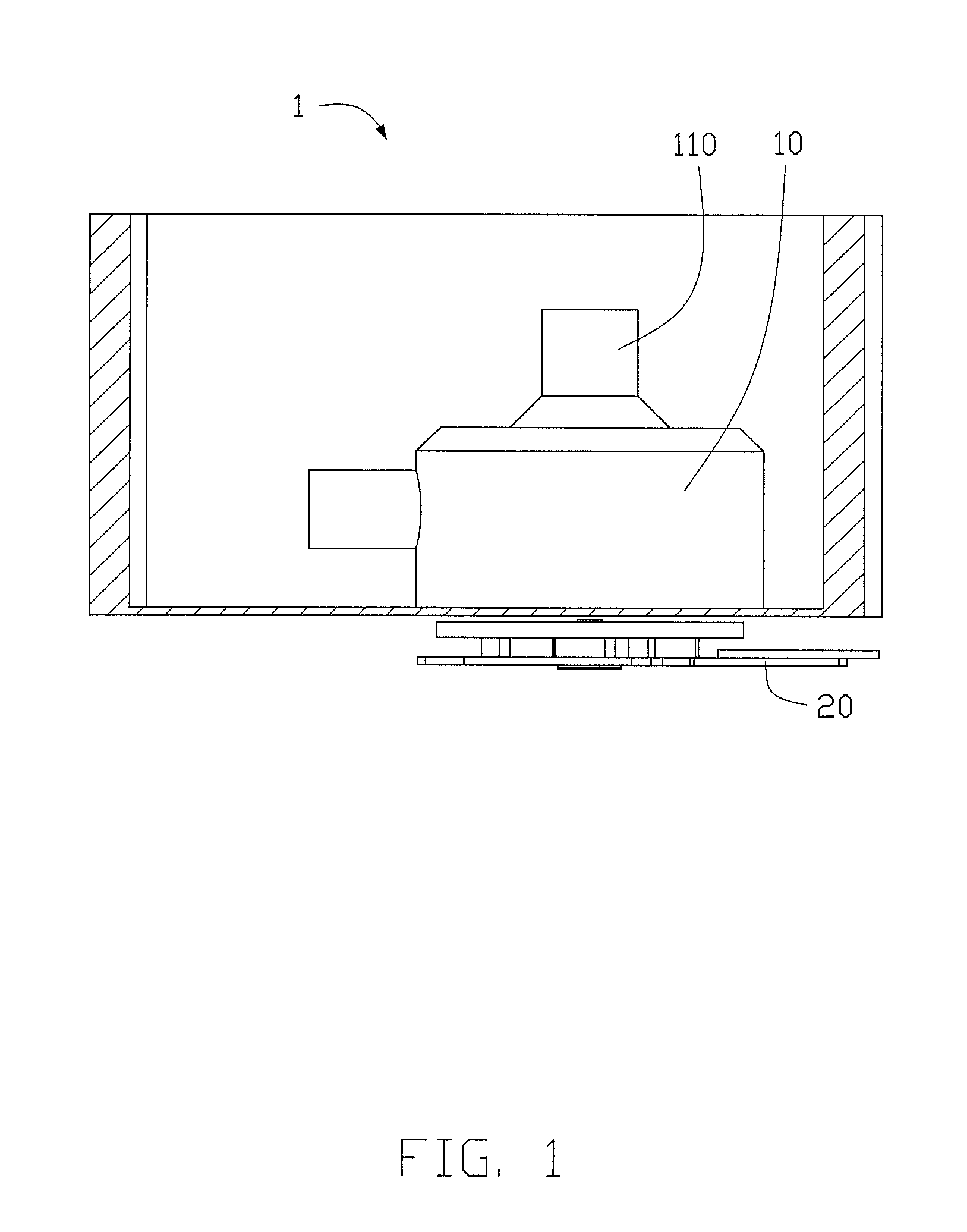
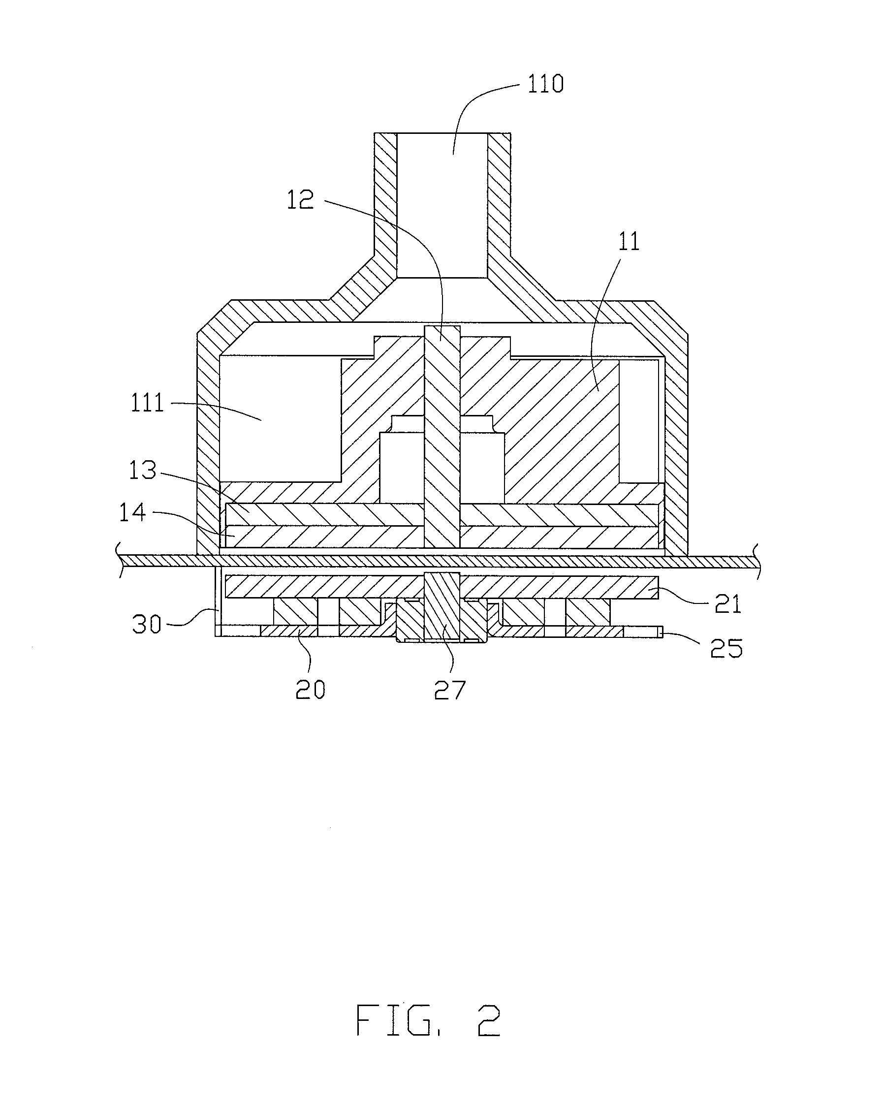
[0027]FIG. 1 is a schematic view of an electric pump 1 in accordance with a preferred embodiment of the invention. FIG. 2 is a sectional view of the pump. The pump 1 includes a pump body 10, a pump magnet 14 disposed in the pump body 10, an impeller 11 disposed in the pump body 10 and fixed with the pump magnet 14, and a disc type electric motor 20 for rotating the pump magnet 14 and the impeller 11 within the pump body 10. In this embodiment, the disc type electric motor 20 is a brushless electric motor. In other embodiments, the disc type electric motor 20 may be a brush type electric motor.

[0028]In this embodiment, the pump magnet 14 and the impeller 11 are rotatably fixed to an inner surface of a bottom of the pump body 10 via a spindle 12 and a bearing (not shown), such that the impeller and pump magnet are able to rotate about the axis of the spindle within the pump body 10. The spindle 12 may or may not be rotatable. The pump 10 includes a water inlet 110 and a water outlet 1...


PUM


Abstract

An electric pump has a pump body, a pump magnet received in the pump body, an impeller received in the pump body and fixed to the pump magnet, and a disc type electric motor. The electric motor includes a stator, disc type coils fixed to a surface of the stator, a rotor rotatably positioned above the coils, and a circuit board electrically connected to the coils. The rotor has a rotor magnet positioned beneath the pump body and magnetically coupled to the pump magnet. When the coils are energized, an axial magnetic field is generated to drive the rotor and, through the magnetic coupling between the rotor magnet and the pump magnet, rotate the impeller.

Description

CROSS REFERENCE TO RELATED APPLICATIONS[0001]This non-provisional patent application claims priority under 35 U.S.C. §119(a) from Patent Application No. 201510253238.X filed in The People's Republic of China on May 18, 2015, the entire contents of which are hereby incorporated by reference.FIELD OF THE INVENTION[0002]This invention relates to an electric pump, and in particular, to an electric pump having a disc type electric motor and to a disc type electric motor.BACKGROUND OF THE INVENTION[0003]Electric pumps for home appliances, such as dish washing machines, generally adopt a direct current electric motor with a radial gap or an induction motor with a radial gap. However, these electric motors have a comparatively long axial dimension and a complicated structure.SUMMARY OF THE INVENTION[0004]Hence there is a desire for an electric pump having a short axial dimension.[0005]Accordingly, in one aspect thereof, the present invention provides an electric pump, comprising: a pump bod...

Claims


Application Information

Patent Timeline
IPC IPC(8): F04D13/06F04D29/42F04D29/22F04D13/02F04D1/00
CPCF04D13/0693F04D13/027F04D29/426F04D29/2205F04D1/00F04D13/0606F04D13/0666
Inventor CHAI, JIELEUNG, CHING HANGPOON, KWONG YIPYU, CHUN KEIYUAN, WEI FENGZHANG, TAOXIAO, SAN YUAN
Owner JOHNSON ELECTRIC INTERNATIONAL AG
Why Eureka
Try Eureka