Heat sink

a technology of heat sink and cylindrical body, which is applied in the direction of indirect heat exchangers, lighting and heating apparatus, and semiconductor/solid-state device details. it can solve the problems of reducing reducing the heat absorption performance of the cooling target object, and reducing the degree of design freedom, excellent heat dissipation effect, and improving the strength of the supporting fin

Active Publication Date: 2016-11-24
JAPAN
View PDF28 Cites 12 Cited by
  • Summary
  • Abstract
  • Description
  • Claims
  • Application Information

AI Technical Summary

Benefits of technology

[0015]In the heat sink according to the invention of the present application, which is configured as described above, the cylindrical body has the opening of which inner and outer sides are opened on the front end and is provided with the through-hole communicating the inner side and the outer side on the side wall at the base end side, and the cylindrical body is provided in the standing manner in the state where the portion at the base end side penetrates through the supporting main body and projects into the gap, the through-hole is opened to the gap, and the portion at the front end side also projects from the surface of the supporting main body at the opposite side to the gap. With this configuration, the cylindrical body can be provided in the standing manner relatively freely in comparison with the conventional configuration in which the supporting main body is made close contact with the cooling target object, and the degree of freedom of design is enhanced. In addition, heat of the cooling target object is dissipated to the outside through the supporting main body and the cylindrical body and, in particular, heat in the gap between the supporting main body and the cooling target object can be also taken into the inner space of the cylindrical body through the through-hole so as to flow to the front end side as heat flow, and be efficiently discharged to the outside through the opening on the front end. Also in the process thereof, the heat is discharged to the outside through a circumferential wall of the cylindrical body. Therefore, the heat sink having an excellent heat dissipation effect can be provided without increasing the number of cylindrical bodies.
[0016]Further, the base end of the cylindrical body is fixed in the state of abutting against the cooling target object. With this configuration, the cylindrical body is made into a stable posture in which an intermediate portion thereof is fixed to the supporting main body and the base end thereof abuts against the cooling target object. Therefore, strength for supporting the cylindrical body is improved so as to enlarge the range of choices for a material, an outer diameter, a thickness dimension, and the like of the cylindrical body. This enables the degree of freedom of design to be improved.
[0017]In addition, the cylindrical body is configured by coupling at least equal to or more than two cylinders including the cylinder at the base end side, which has the through-hole and is fixed to the supporting main body, and the cylinder at the front end side, which has the opening, to each other in the axial direction in the state where the inner spaces of the cylinders communicate with each other, and the atmosphere containing heat emitted from the supporting main body is capable of being made to flow into the cylindrical body through the through-hole, circulate in the inner space of the cylindrical body, and be released to outside through the opening on the front end. With this configuration, the plurality of cylinders configuring the cylindrical body can have configurations in accordance with respective positions while materials and structures of the cylinders are made different. Therefore, a heat sink having excellent heat dissipation performance can be provided at reduced cost without increasing the number of cylindrical bodies.
[0018]Further, the outer diameter of the cylinder at the base end side is set to be smaller than the outer diameter of the cylinder at the front end side and the cylinder at the base end side is made of the material having higher heat conductivity than the material of the cylinder at the front end side. With this configuration, the outer diameter of the cylinder at the base end side, which is fixed to the supporting main body, is set to be smaller than the outer diameter of the cylinder at the front end side so as to prevent lowering in the strength of the supporting main body itself for fixing the cylinder at the base end side (note that the strength lowers when the hole for caulking fixing is large). In addition, for coping with a point that the cylinder at the base end side is reduced in thickness in order to maintain the inner space of the cylindrical body, the material having excellent heat conductivity is selected so as to complement a heat absorbing effect for heat from the supporting main body. With this, excellent heat absorbing performance and heat conductivity can be maintained.
[0019]In addition, for example, a material having heat conductivity lower than that of the cylinder at the base end side but reduced in cost can be selected for the cylinder at the front end side. With this, the cylinder at the front end side can have a large dimension, thereby ensuring a cross-sectional area thereof. In particular, the cylinder at the base end side, which is made of an expensive material, can be set to have the minimum length having a site at which it is fixed to the supporting main body, a site at which the through-hole is provided, and a site at which the cylinder is coupled thereto and another portion can be configured by the cylinder made of a relatively inexpensive material. This enables reduction in cost while enhancing the heat absorbing performance and the heat conductivity as described above.
[0020]Further, the plurality of protrusions extending along the axial direction are provided on the outer circumferential surface of the cylinder at the front end side at an interval in the circumferential direction. Therefore, the surface area is increased and heat dissipation performance is enhanced. This configuration can enhance an effect of dissipating the hot air taken into the inner space to the outside through a pipe wall in a process in which the hot air circulates to the front end side. As a result, the circulation of the hot air in the inner space of the cylindrical body is further accelerated, thereby further enhancing a series of heat dissipation effect including taking of the hot air at the base end side, movement thereof to the front end side, and the release thereof.

Problems solved by technology

However, the increase in the number of fins lowers strength of the supporting plate supporting the fins and thereby lowers strength for supporting the fins, resulting in a problem.
Further, when the fins are crowded, hot air is accumulated between the fins.
In particular, the hot air is accumulated near the supporting plate at the base end side and heat absorbing performance from the cooling target object also lowers.
This causes certain limitation on the improvement in the heat dissipation performance.
An air blower such as a fan can be separately provided so as to forcibly dissipate the hot air between the fins but it is limited.
The air blower cannot be provided in some heat sinks because of increase in weight, space, and the like.

Method used


Image

  • Heat sink
  • Heat sink
  • Heat sink

Examples


first embodiment

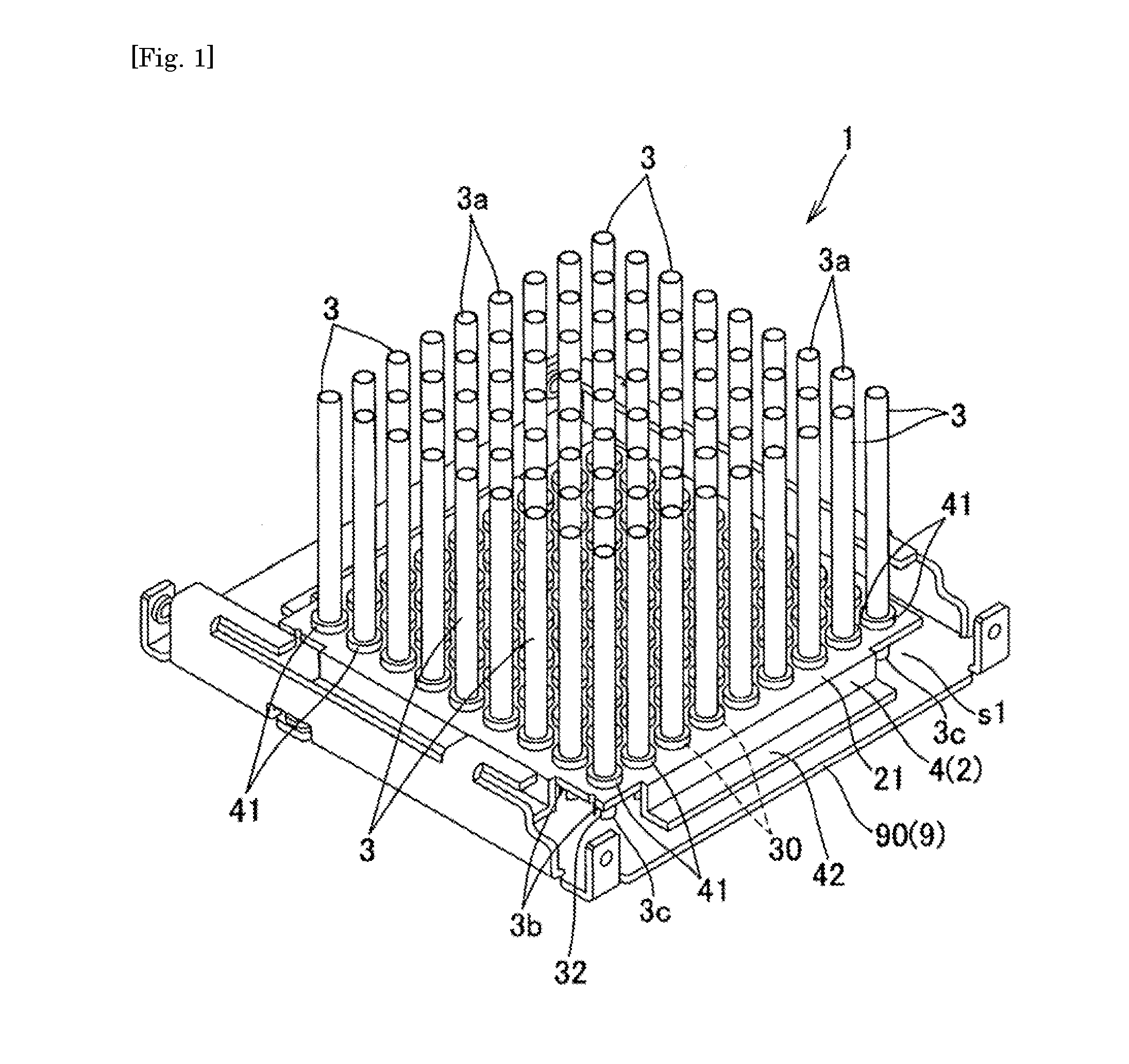
[0038]First, the invention will be described with reference to FIG. 1, FIG. 2, FIG. 3, FIG. 4 and FIG. 5.

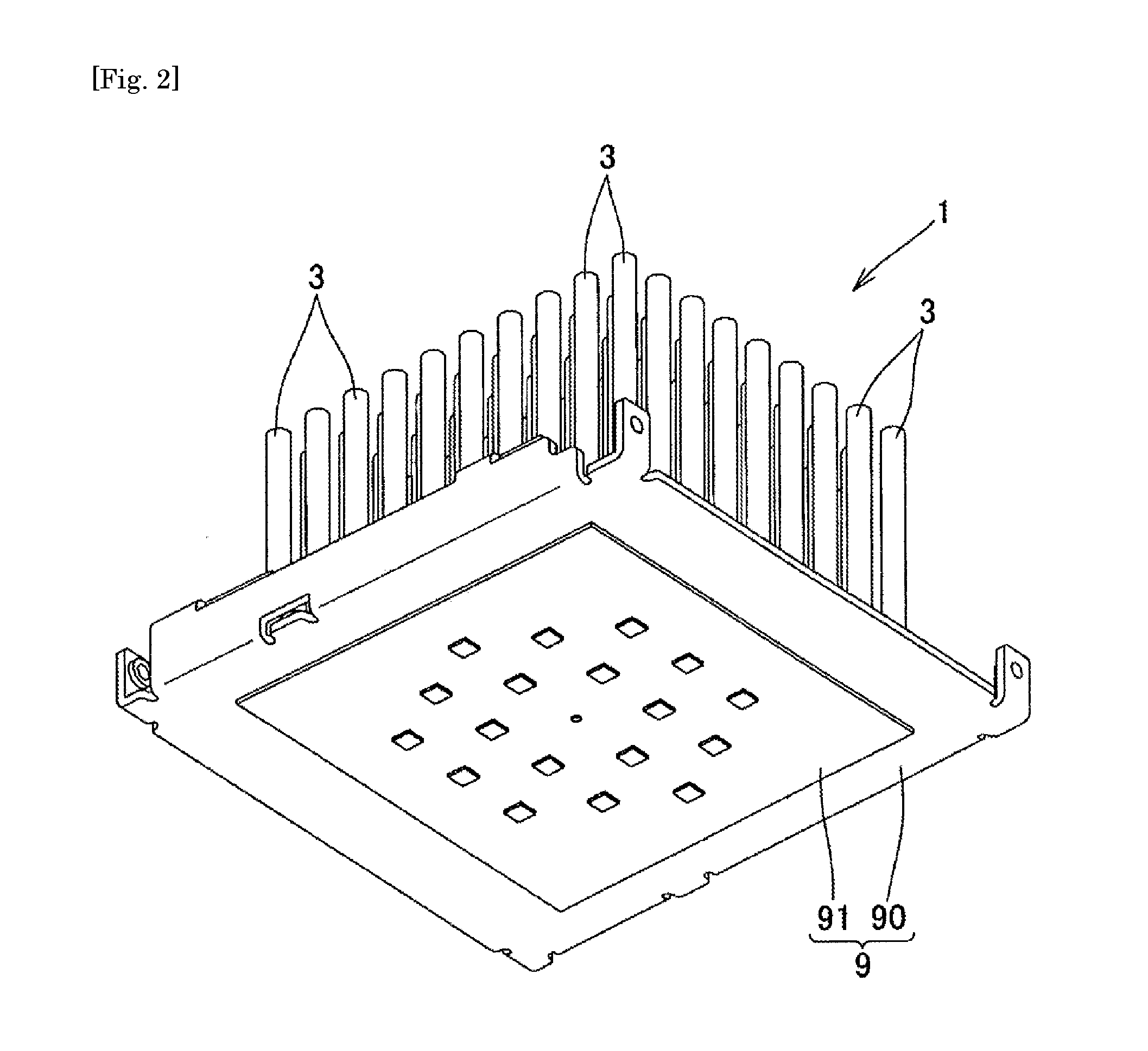
[0039]As illustrated in FIG. 1, FIG. 2 and FIG. 3, a heat sink 1 in the embodiment includes a supporting main body 2 made of a material having excellent heat conductivity and one or a plurality of cylindrical body(ies) 3 that is(are) provided on the supporting main body 2 in a standing manner and is(are) made of a material having excellent heat conductivity. The supporting main body 2 is fixed to a cooling target object 9 with a gap s1 ensured therebetween. As the materials of the supporting main body 2 and the cylindrical body 3, which have excellent heat conductivity, metal materials such as aluminum, copper, and iron are preferable, for example.

[0040]The cooling target object 9 includes an LED substrate 91 configuring the LED lighting device and a housing plate 90 made of metal to which the LED substrate 91 is attached in this example. The supporting main body 2 is fixed to th...

second embodiment

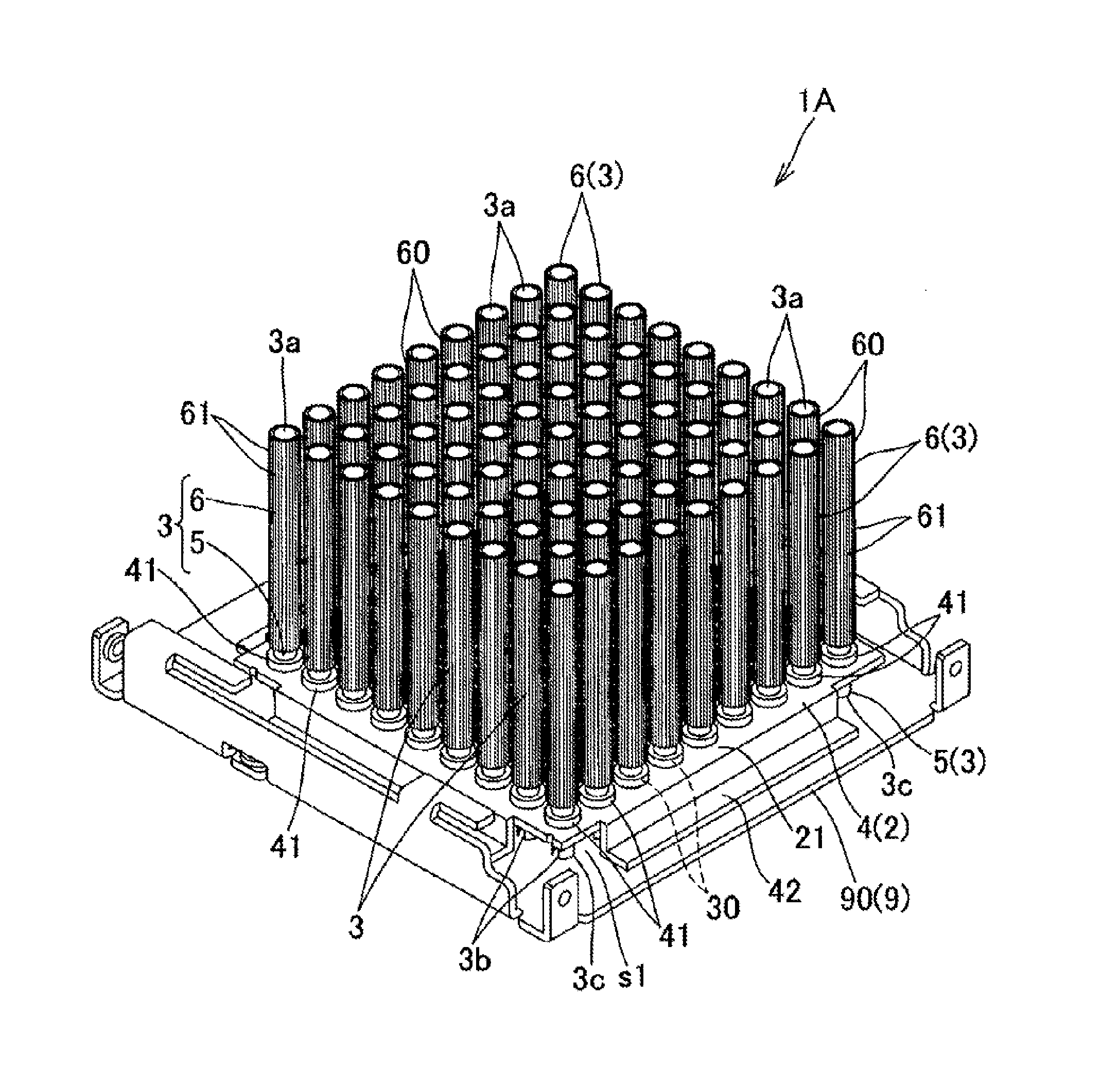
[0049]Next, the invention will be described with reference to FIG. 6, FIG. 7, FIG. 8(a) and FIG. 8(b).

[0050]As illustrated in FIG. 6, FIG. 7, FIG. 8(a) and FIG. 8(b), in a heat sink 1A in the embodiment, each cylindrical body 3 is configured by coupling equal to or more than two cylinders including a cylinder 5 at the base end side, which has the through-hole 3b and is fixed to the supporting main body 2, and a cylinder 6 at the front end side, which has the opening 3a on the front end, to each other in the axial direction in a state where inner spaces of the cylinders communicate with each other. With this coupling configuration, the cylinders can have configurations in accordance with respective positions thereof while materials and structures of the cylinders are made different.

[0051]In the embodiment, the outer diameters of the cylinders 5 at the base end side, which are fixed to the supporting main body 2 (supporting plate 4), are set to be smaller than the outer diameters of t...

third embodiment

[0059]Next, the invention will be described with reference to FIG. 9, FIG. 10, FIG. 11, FIG. 12(a), FIG. 12(b) and FIG. 13.

[0060]As illustrated in FIG. 9, FIG. 10 and FIG. 11, in a heat sink 1B in the embodiment, the supporting main body 2 is fixed to the cooling target object 9 in a close contact state with no gap therebetween. To be specific, the surface of the supporting plate 4 as the supporting main body 2 to which the cylindrical bodies 3 are fixed at the opposite side to the surface thereof on which the cylindrical bodies 3 are provided in the standing manner is fixed to the housing plate 90 as the cooling target object 9 in a surface contact state. With this, heat transferred from the LED substrate 91 to the housing plate 90 efficiently moves to the supporting plate 4 so as to be efficiently dissipated through the surface of the supporting plate 4 and the cylindrical bodies 3 as will be described later.

[0061]In the same manner as in the second embodiment, each the cylindrica...


PUM


Abstract

To provide a heat sink capable of enhancing heat dissipation performance.
Cylindrical bodies 3 have openings 3a of which inner and outer sides are opened on front ends and are provided with through-holes 3b communicating the inner side and the outer side on side walls at the base end side. The cylindrical bodies 3 are provided in a standing manner in a state where portions at the base end side penetrate through a supporting main body 2 and project into a gap s1, the through-holes 3b are opened to the gap s1, and portions at the front end side also project from the surface of the supporting main body 2 at the opposite side to the gap s1. An atmosphere in the gap s1, which contains heat from a cooling target object 9, is capable of being made to flow into the cylindrical bodies 3 through the through-holes 3, circulate in inner spaces of the cylindrical bodies 3, and be released to the outside through the openings 3a on the front ends.

Description

TECHNICAL FIELD[0001]The present invention relates to a heat sink that is attached to a cooling target object and dissipates heat which is transferred from the cooling target object into the air.BACKGROUND ART[0002]As a heat sink of this type, conventionally, a heat sink including a supporting plate that makes close contact with and is fixed to a cooling target object and is made of a material having excellent heat conductivity, and a plurality of plate-like, columnar, or cylindrical fins that are provided on the supporting plate in a standing manner and are made of a material having excellent heat conductivity has been provided (for example, see Patent Documents 1 and 2). The disclosed heat sink is configured to dissipate heat transferred to the supporting plate from the cooling target object into the air through the surfaces of the fins. For example, in recent years, light-emitting diode (LED) lighting has been widely spread and high-output LED lighting such as lighting for a ware...

Claims


Application Information

Patent Timeline
Patent Type & Authority Applications(United States)
IPC IPC(8): F28F1/20F28F13/14F28F9/013
CPCF28F2215/08F28F2275/122F28F1/20F28F2215/06F28F13/14F28D2021/0029F28F9/0131F21V17/12F21V29/503F21V29/83F21V29/89H01L21/4882H01L23/3677F28F2215/04F28F2215/10
Inventor WATANABE, HIDEMITSUWATANABE, HIROYUKIWATANABE, TAKAFUMI
Owner JAPAN
Why Eureka
Try Eureka