Eye and head tracking device

a head tracking and eye technology, applied in the field of eye and head tracking, can solve the problems of apparatus wearing like eyeglasses, apparatus wearing like glasses, and apparatus wearing over glasses of users

Active Publication Date: 2016-11-24
SHAZLY TAREK A +1
View PDF18 Cites 32 Cited by
  • Summary
  • Abstract
  • Description
  • Claims
  • Application Information

AI Technical Summary

Benefits of technology

[0017]The present invention serves to meet these needs, in addition to having other beneficial properties such as compactness, accuracy and non-blocking of the eye view. According to one embodiment of the present invention, a compact apparatus comprises (1) at least one optoelectronic array sensor or optical flow sensor; (2) a body configured to support the optoelectronic array sensor with focusing means along with a source of light with collimating means in front of an eye of a user; (3) an optical focusing means to focus an image of the ocular surface of the user on the optoelectronic array sensor; (4) a focusing lens with a source of light; (5) means to detect blinking; and (6) a driver configured to receive signals from the sensor and to determine eye movements based on the received signals. The focusing means may include a plus powered focusing lens, mirror or pinhole. The apparatus may further comprise a means to detect user's additional input and gestures. The terms “optoelectronic array sensor” and “optical flow sensor” may be used interchangeably herein.
[0033]The apparatus may further comprise a gyroscopic sensor attached to the body of the device as a means to detect user's additional input and gestures. The gyroscopic sensor is mounted on the body of the device. As the body of the device in the frame moves in unity with the head of the user, the gyroscopic sensor senses the movement of the user's head in the horizontal, vertical and rotational directions. The digital data generated by the gyroscopic sensor is transmitted via wired or wireless means to the external device such as a computer. The computer software uses the head movement tracking data generated by the gyroscopic sensor in conjunction with the head tracking data generated by the optoelectronic array sensor. When the user fixates on an object and moves his or her head, the vestibulo-ocular reflex moves the eyes in opposite direction so that the optoelectronic array sensor sensed eye tracking data can be processed by the external device software can be used for head movement tracking. The data generated by the gyroscopic sensor as well as the optoelectronic array sensor can be further processed by the external device software in a mathematical way to use one or both sets of data to improve the accuracy of head movement tracking.

Problems solved by technology

The apparatus may be wearable like eyeglasses.
The apparatus may be wearable directly on the face of the user.
The apparatus may be wearable over the glasses of the user.

Method used


Image

  • Eye and head tracking device
  • Eye and head tracking device
  • Eye and head tracking device

Examples


Embodiment Construction

[0052]An example embodiment of the present invention and its potential advantages are understood by referring to FIGS. 1 through 5 of the drawings.

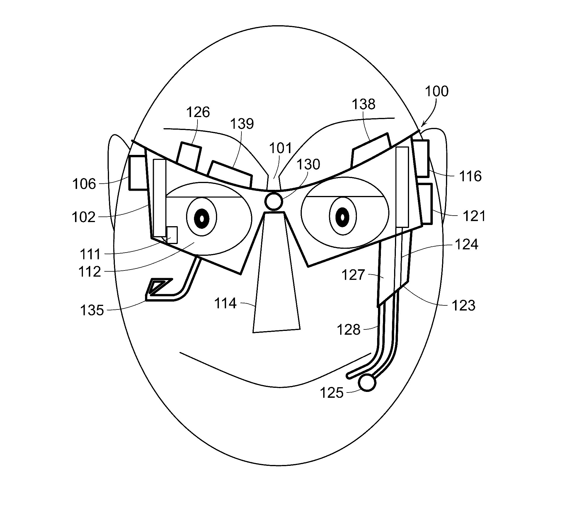
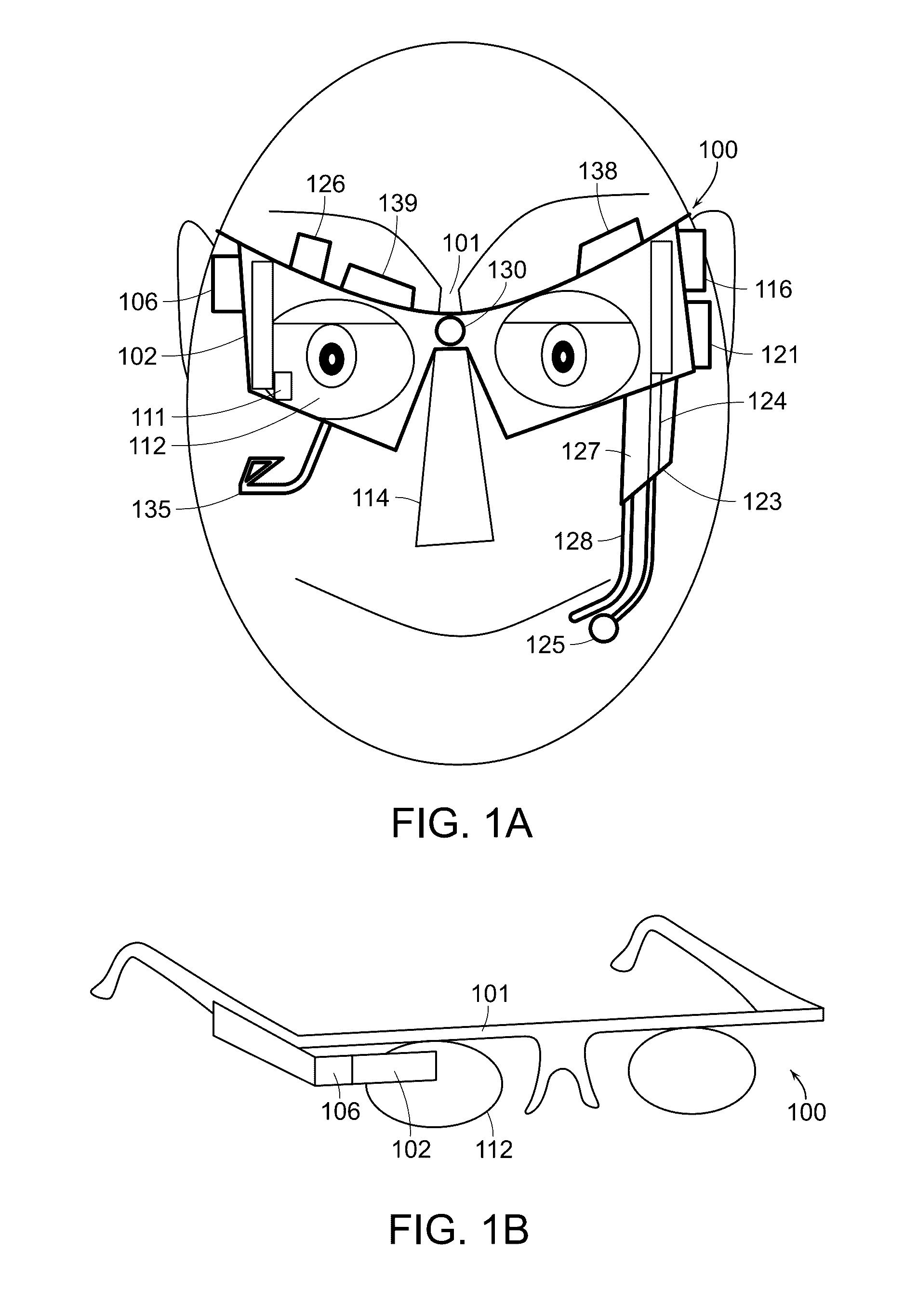
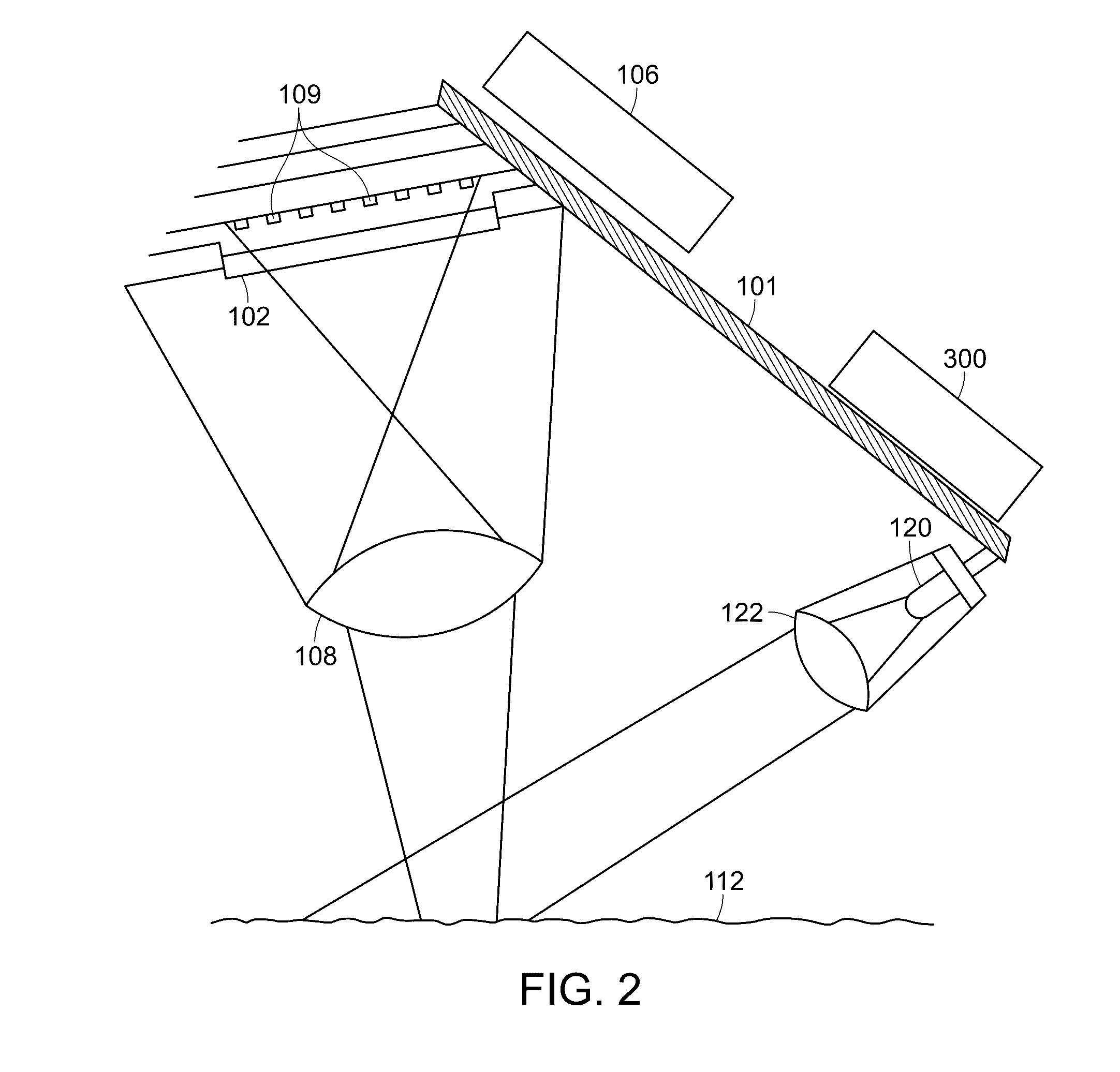
[0053]FIGS. 1A and 1B shows a schematic drawing of a head-worn apparatus 100, when seen from front. The apparatus 100 comprises an optoelectronic array sensor 102 supported by a body 101 or frame in front of an eye 112 of a user 110. The apparatus 100 further comprises a driver 106 configured to receive signals from the optoelectronic array sensor 102 and to determine eye movements based on the received signals. The driver 106 can detect relative motion of the eye 112 based on the offset of the pattern of imperfections of the surface of the eye 112 between successive frames obtained by the sensor 102.

[0054]The apparatus may be wearable by the user. The apparatus may be wearable like eyeglasses.

[0055]In an example embodiment and in FIG. 1, the body 101 is supported by the nose 114 of the user and / or by one or two ears 116 of the user.

[0056...


PUM


Abstract

An apparatus and method of use for tracking eye and head movement comprising (1) at least one optoelectronic array sensor or optical flow sensor formed of a plurality of optoelectronic sensor cells; (2) a body configured to support the optoelectronic array sensor with focusing means along with a source of light with collimating means in front of and in proximity to an eye of a user; (3) an optical focusing means to focus an image of the ocular surface of the user on the optoelectronic array sensor; (4) a focusing lens with a source of light; (5) a means to detect blinking; (6) a driver configured to receive signals from the sensor array to generate coordinate signals corresponding to changes in the position of the ocular surface relative to the sensor array; and (7) a means to detect user's additional input and gestures.

Description

RELATED APPLICATIONS[0001]This application is a National Stage Application under 35 USC 371 of Application No. PCT / US2015 / 013220 filed Jan. 28, 2015, which claims priority to U.S. Provisional Application No. 61 / 932,849 filed Jan. 29, 2014. The entire contents of the above application are hereby incorporated by reference as though fully set forth herein.BACKGROUND[0002]The present application generally relates to eye and head tracking. In particular, though not exclusively, the present application relates to non-contact eye and head tracking.[0003]Eye movements of human beings are mediated by different voluntary and involuntary mechanisms. Different parts of the nervous system are responsible for starting, maintaining and terminating eye movements. Fixation is the maintaining of the visual gaze on a single location. Other parts of the nervous system are responsible for maintaining eye fixation on an object regardless of the head position in space.[0004]The vestibulo-ocular reflex (VO...

Claims


Application Information

Patent Timeline
Patent Type & Authority Applications(United States)
IPC IPC(8): G06F3/01A61B5/11G02C11/00G06T11/60G06K9/00A61B3/113G06F3/03
CPCG06F3/013A61B3/113A61B5/1114G06F3/012G06F3/0304G06T2207/30204G06F3/017G06K9/00604G06K9/00335G02C11/10A61B2562/0219G06T11/60A61B5/0077G02B2027/0178G06V40/19G06V40/20
Inventor SHAZLY, TARKE AABDELWAHED, SALWA A
Owner SHAZLY TAREK A
Why Eureka
Try Eureka