
Ergonomic Chair

a chair and ergonomic technology, applied in the field of chairs and stools, can solve the problems of affecting the use of the chair, so as to improve the strength, endurance and flexibility of the user, and reduce fatigue and back pain. , the effect of improving circulation

Active Publication Date: 2016-12-01
MARK DARREN WILLIAM
View PDF3 Cites 12 Cited by
  • Summary
  • Abstract
  • Description
  • Claims
  • Application Information

AI Technical Summary

Benefits of technology

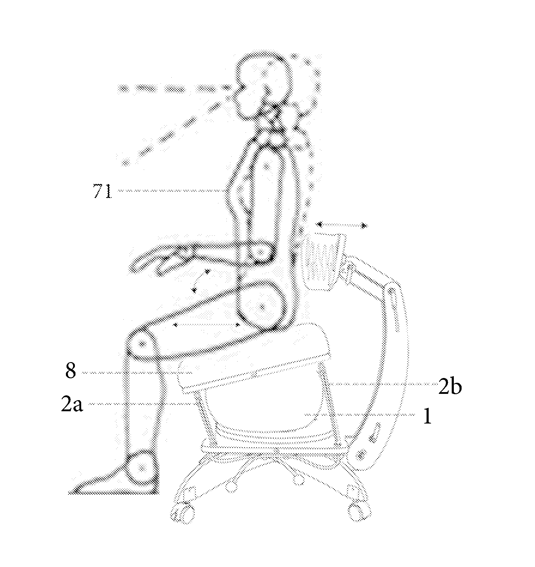
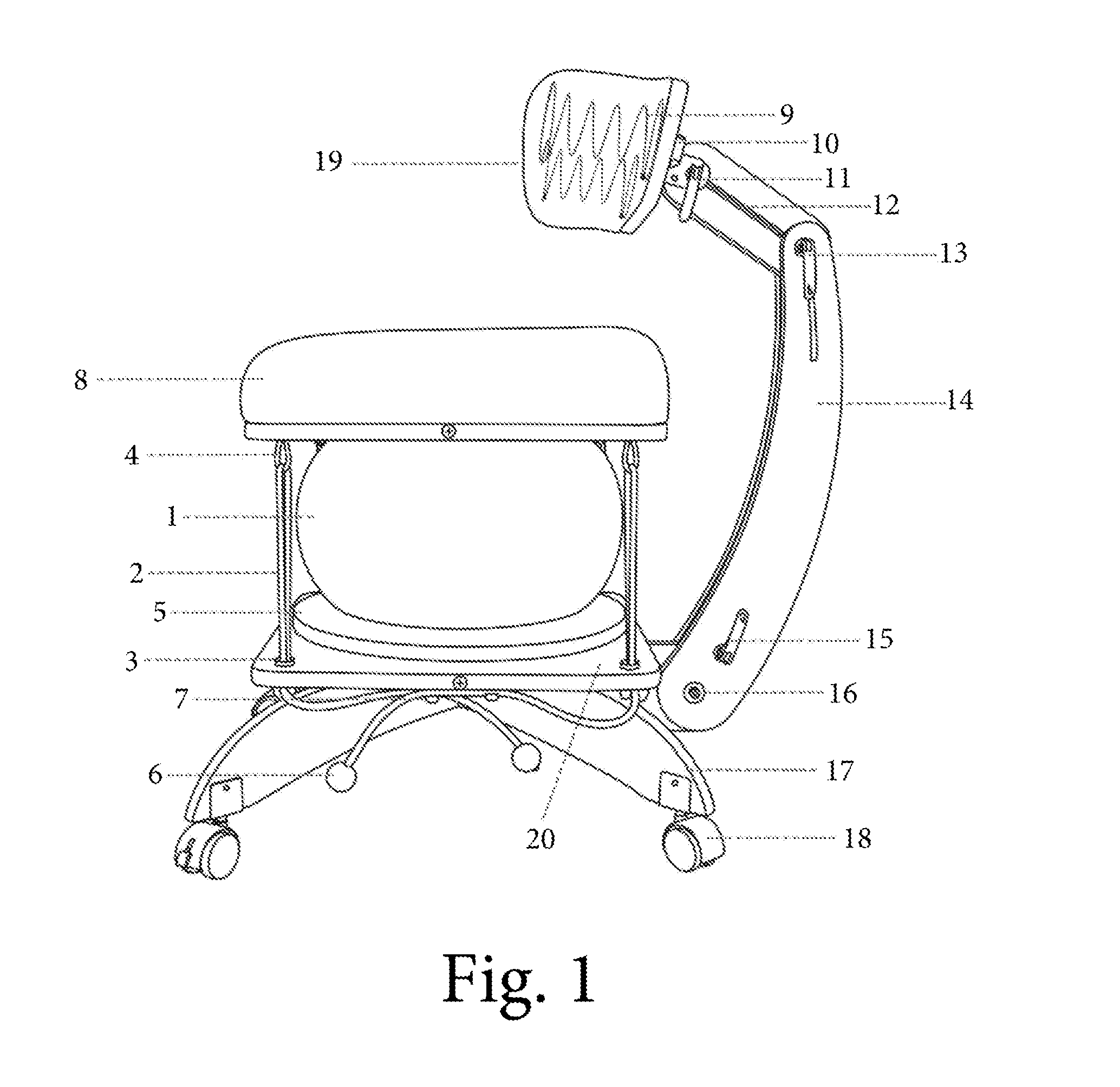
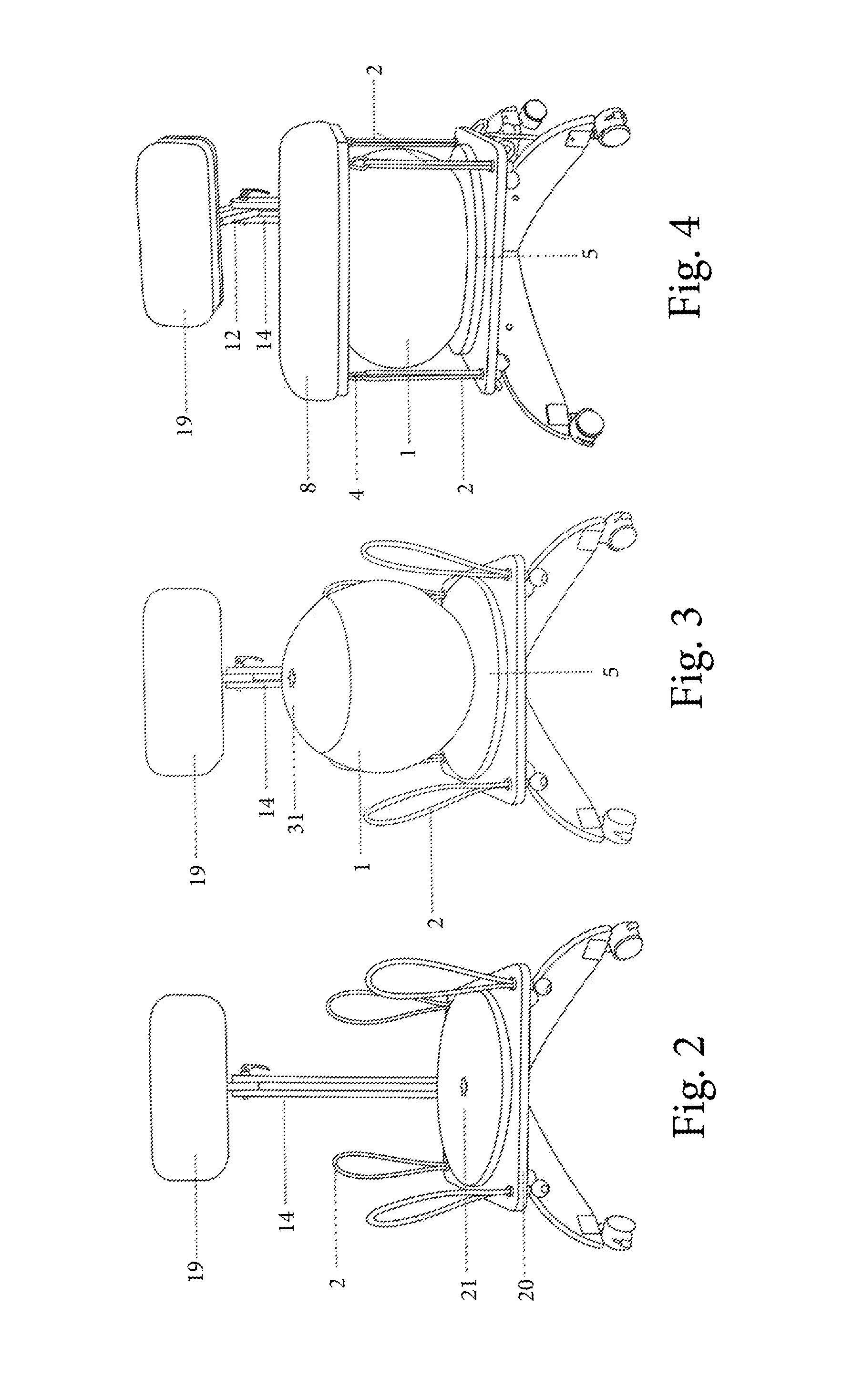
The present invention is an ergonomic chair that improves strength, endurance, and flexibility of the user while reducing fatigue and back pain. The chair has a contoured seat cushion mounted on an exercise ball with four tension-adjustable elastic cords. The elastic cords hold the seat cushion in a counter-tensioned balance and provide positive resistance for the muscles of the sitter to push against. The chair is height adjustable, and the ball is centered on the lower platform by means of an upper and lower fastener, which also serves both a decorative and protective function. The chair also has an optional lumbar support and a dynamic lumbar cushion to encourage movement even when the lumbar back support is engaged.

Problems solved by technology

Most recently exercise balls have been used, either alone or within a chair “frame” for core strengthening but are problematic because when used alone they roll away, deflate, don't provide enough stability, and most significantly, don't provide appropriate weight distribution on the coccyx, femurs, gluteal region, and through recent studies, have been found that they do not engage the core muscles more than a traditional chair.
However, a great number of people have moderate-to-severe back problems.
The primary problem with all existing chair forms, is that the seating platform, whether an inflatable ball, fixed, or otherwise ‘ergonomic’ is fixed in one plane, so that the angle of the spine, legs and hips, are captive for long periods of sitting, with no ability to change the sitting position, creating constant compressive force on the vertebrae, causing pain to the lower back, limiting circulation and virtually eliminating active muscle engagement.

Method used


Image

  • Ergonomic Chair
  • Ergonomic Chair
  • Ergonomic Chair

Examples


Embodiment Construction

[0017]The detailed description set forth below in connection with the appended drawings is intended as a description of presently preferred embodiments of the invention and does not represent the only forms in which the present invention may be constructed and / or utilized. The description sets forth the functions and the sequence of steps for constructing and operating the invention in connection with the illustrated embodiments.

[0018]The present invention features a chair having a contoured seat cushion mounted on top of an exercise ball with four tension-adjustable elastic cords such as bungee cords. The shock cords attach to the underside of the seat cushion by looping through spring-eye carabiner type hooks, and passing through grooved locking tubes with v-channels for adjusting the bungee cord tension. The ball sits on top of a swivel plate, so that dynamic motion and counterbalancing are attainable for a variety of ergonomically beneficial seating styles.

[0019]The chair has an...


PUM


Abstract

A chair having a contoured seat cushion mounted on top of an exercise ball with four tension-adjustable elastic cords such as bungee cords is provided. The shock absorbing cords may attach to the underside of the seat cushion by looping through spring-eye carabiner type hooks, and may pass through grooved locking tubes with v-channels for adjusting the cord tension. The ball may sit on top of a swivel plate, so that dynamic motion and counterbalancing are attainable for a variety of ergonomically beneficial seating styles.

Description

FIELD OF THE INVENTION[0001]The present invention pertains to chairs and stools, and more particularly, to ergonomic chairs, providing comfortable seating that not only alleviates back problems but encourages core strengthening, blood circulation, muscular involvement, for overall back, muscular and circulatory health.BACKGROUND[0002]There are a myriad of chair designs extant, many of which claim to be more efficient, more comfortable, or more therapeutic than others. Most recently exercise balls have been used, either alone or within a chair “frame” for core strengthening but are problematic because when used alone they roll away, deflate, don't provide enough stability, and most significantly, don't provide appropriate weight distribution on the coccyx, femurs, gluteal region, and through recent studies, have been found that they do not engage the core muscles more than a traditional chair.[0003]Prior to the ball chairs, foam, rubber and mesh materials have been used in chair manu...

Claims


Application Information

Patent Timeline
IPC IPC(8): A47C7/56A47C7/60A47C3/18A47C7/40A47C7/00
CPCA47C7/566A47C7/40A47C7/60A47C3/18A47C7/002A47C7/006A47C3/0252A47C7/402A47C9/005
Inventor MARK, DARREN WILLIAM
Owner MARK DARREN WILLIAM
Learn More