Robot system for monitoring contact force of robot and human

Active Publication Date: 2016-12-01
FANUC CORP
View PDF6 Cites 11 Cited by
  • Summary
  • Abstract
  • Description
  • Claims
  • Application Information

AI Technical Summary

Benefits of technology

[0015]The present invention provides a robot system which can suppress to a minimum, the risk

Problems solved by technology

Accordingly, there is the risk that the force sensor may not detect contact between a human and the robot after such an adjustment as the force applied to the robot which could previously have been detected by the force sensor, needs to be larger.
As a result, there is an increased risk of the robot c

Method used


Image

  • Robot system for monitoring contact force of robot and human
  • Robot system for monitoring contact force of robot and human
  • Robot system for monitoring contact force of robot and human

Examples


first embodiment

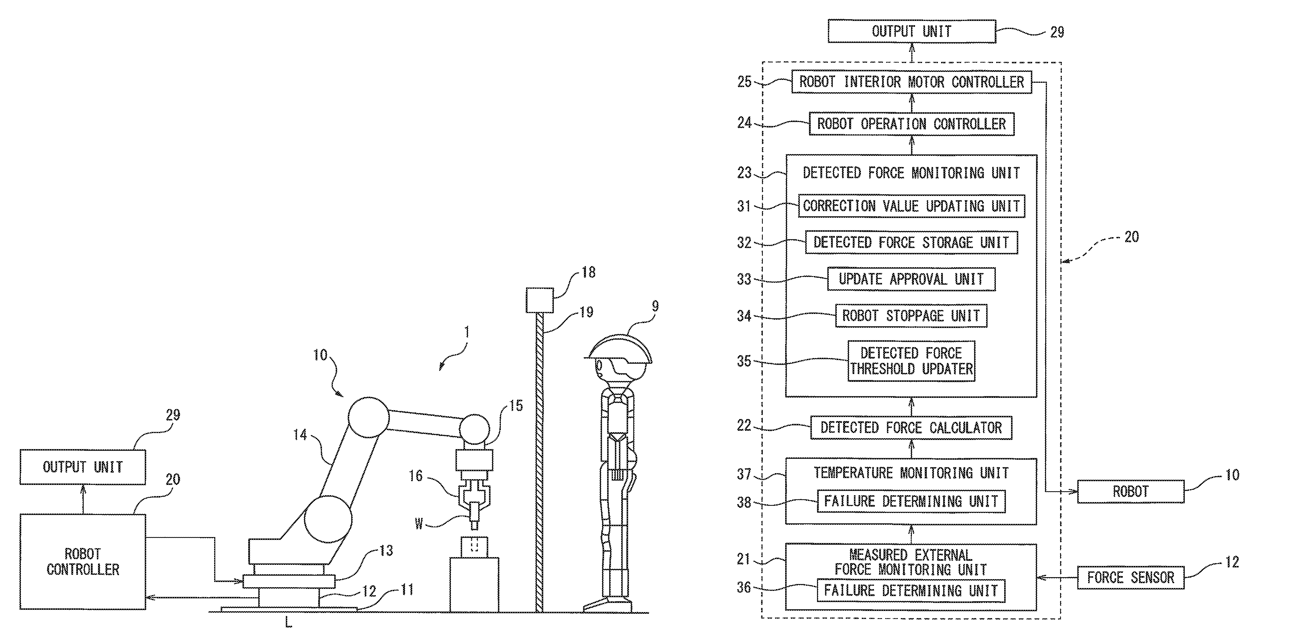
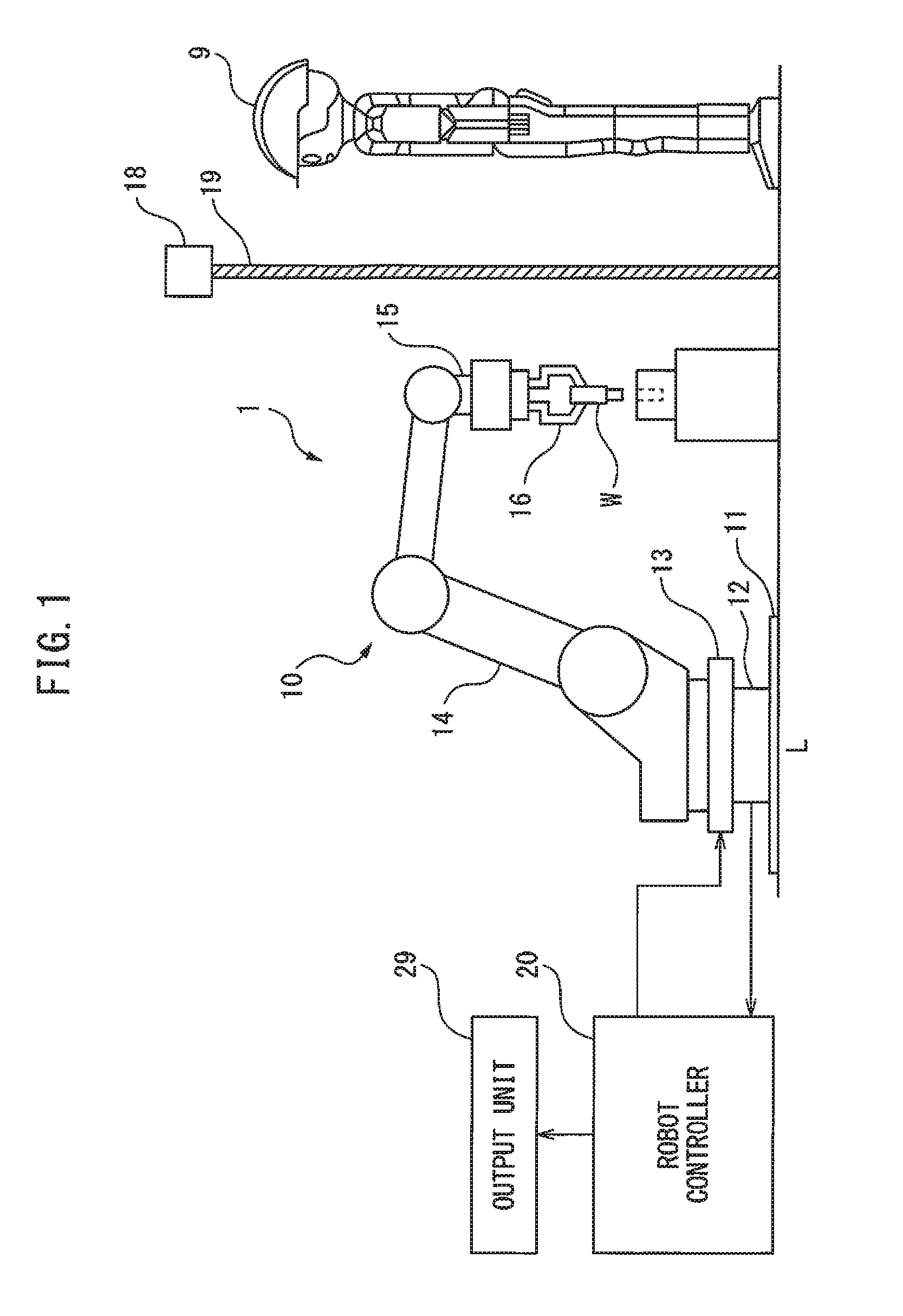
[0033]FIG. 1 is a side view of the human cooperative robot system according to the first embodiment. In the human cooperative robot system 1 illustrated in FIG. 1, a human 9 and a robot 10 approach each other in order to carry out cooperative work.

[0034]The robot 10 is a vertical multi-joint type manipulator. In order to install the robot 10 on the floor L, a fixing plate 11 is secured onto the floor L. Further, a force sensor 12 is provided on the fixing plate 11, furthermore a robot base 13 of the robot 10 is provided on the force sensor 12. The force sensor 12 is used as a load detector for detecting the load applied to the robot 10. Inside the force sensor 12, a strain detector, for example a strain gauge, specifically a semiconductor strain gauge, is provided for detecting the strain on force sensor 12 caused by an external force. More specifically, the force sensor 12 is provided with a force sensor body and a strain gauge attached to the force sensor body. Such a force sensor...

second embodiment

[0056]Next, the second embodiment will be described. Note that, in each of the embodiments including the second embodiment described below, the structural elements which are the same as those in the first embodiment will have the same reference numerals and only points different to the first embodiment will be described.

[0057]In the second embodiment, with respect to the first embodiment, the failure determining unit 38 of the temperature monitoring unit 37 calculates the temperature rise amount of the detected temperature output from the temperature sensor in the force sensor 12, over a predetermined period of time. The failure determining unit 38 determines whether or not the temperature rise amount exceeds a predetermined threshold. If the threshold is exceeded, the robot 10 is immediately stopped.

[0058]For example, if the predetermined time period is one minute and the temperature rise amount of the detected temperature output from the temperature sensor of the force sensor 12 e...

third embodiment

[0060]Next, the third embodiment will be described. FIG. 3A is a perspective view of the force sensor 12 of the third embodiment. FIG. 3B is an enlarged view of the portion enclosed by the dotted line X in FIG. 3A, and FIG. 3C is a side view of the force sensor illustrated in FIG. 3A.

[0061]The force sensor 12, as illustrated, in FIG. 3A, comprises a force sensor body 200 and a plurality of load detection elements, for example, strain gauges 212 and 222 attached to the force sensor body. Furthermore, as illustrated in FIG. 3B, the force sensor 12 has a plurality of load detection portions 211 and 221. In the first load detection portion 211, two temperature sensors 213 and 214 are arranged near the one strain gauge 212. Similarly, in the second load detection portion 221 two temperature sensors 223 and 224 are arranged near the one strain gauge 222. Note that, regarding the position the two temperature sensors 213 and 214 (or 223 and 224) are arranged, instead of the positions illust...


PUM


Abstract

The human cooperative robot system according to the present invention includes a robot, a force sensor detecting a load applied to a robot, and a robot controller controlling the robot. The force sensor includes at least one temperature detection element detecting temperature, incorporated therein. The robot controller determines whether or not to stop the operation of the robot based on the detected temperature output from the temperature detection element.

Description

BACKGROUND ART[0001]1. Technical Field[0002]The present invention relates to a human cooperative robot system which carries out work in the same workspace as a human. More specifically, the present invention relates to a robot system which monitors the contact force of a robot and a human and ensures the safety of the human.[0003]2. Description of the Related Art[0004]With respect to an industrial robot, in order to ensure the safety of humans, a safety fence is set up around the moveable area of a robot and humans are restricted from entering the area in which the robot can move. However, in recent years, instead of a safety fence, industrial robots on which certain measures have been carried out to ensure sufficient safety thereof to humans have allowed work to be carried out in a workspace shared by humans and robots. As a result, the desire for these types of robot, namely, human cooperative robots has increased.[0005]By using a human cooperative robot system, separate work can ...

Claims


Application Information

Patent Timeline
IPC IPC(8): B25J9/16G01L5/00G01L5/22B25J13/08
CPCB25J9/1694B25J13/085G01L5/226G01L5/0052B25J13/087B25J19/06B25J9/1674G01L5/1627
Inventor NAKAYAMA, KAZUTAKAFUJITA, JUNYAINOUE, YOUICHI
Owner FANUC CORP
Why Eureka
Try Eureka