Drive system control device for working vehicle

a technology of control device and working vehicle, which is applied in the direction of process and machine control, instruments, etc., can solve the problems of engine stall risk, engine load is rapidly increased, engine output torque cannot follow, etc., and achieves the effect of improving workability in the working vehicle, torque and torque increas

Inactive Publication Date: 2014-09-16
YANMAR POWER TECHNOLOGY CO LTD
View PDF11 Cites 4 Cited by
  • Summary
  • Abstract
  • Description
  • Claims
  • Application Information

AI Technical Summary

Benefits of technology

[0011]According to the drive system control device of the working vehicle of the first aspect of the present invention, in the working vehicle provided with the engine which is mounted to the travel machine body, the common rail type fuel injection device which injects the fuel to the engine, and the continuously variable transmission which shifts the power from the engine, since the drive system control device changes the engine operating point relating to the rotating speed and the torque of the engine in such a manner that the rotating speed of the engine comes to the rotating speed in the high speed side that the overload is dissolved, and changes and regulates the change gear ratio of the continuously variable transmission in such a manner that the vehicle speed of the travel machine body does not change, in the case that the overload acts on the engine having the low rotating speed, it is possible to prevent the output torque from running short in relation to a rapid rise of the engine load, and it is possible to avoid generation of black smoke, knocking and engine stall. On the other hand, it is possible to maintain the vehicle speed of the travel machine body as it is. Therefore, it is possible to achieve an effect of improving a workability in the working vehicle at a time of traveling at a low speed.
[0012]According to the invention of the second aspect, since the reverse droop control of the engine is executed under the condition that the rotating speed is equal to or less than the predetermined rotating speed and the torque is equal to or more than the predetermined torque, and the engine operating point for dissolving the overload is decided on the basis of the relationship between the torque at the overloading time and the reverse droop characteristic, the rotating speed and the torque are both increased by executing the reverse droop control in relation to the rapid rise of the engine load. Accordingly, as well as it is possible to apply tenacity to the engine output, there can be achieved an effect of securely suppressing a risk of the engine stall.
[0013]Since the invention of the third aspect is structured such that the engine operating point for dissolving the overload is equal to the engine operating point at the overloading time in the output horsepower, and the engine load rate at the engine operating point for dissolving the overload is equal to or less than the predetermined value, the output horsepower of the engine is employed as a reference of the change of the engine operating point. Therefore, there can be achieved an effect of simply and accurately carrying out the vehicle speed maintenance of the working vehicle.

Problems solved by technology

In the case mentioned above (in the case that the rotating speed of the engine is in a low speed range), if a lot of load is applied to the ground working machine, for example, for the reason that the farm field is hard or the like, an engine load is rapidly increased, however, a response of an output torque of the engine can not follow so as to lapse into an output torque short, so that there has been a risk that a knocking is generated while discharging black smoke or an engine stall is caused.
However, since the rotating speed increases in proportion to an increase of the output torque in the reverse droop control, there is a possibility that the vehicle speed of the tractor becomes higher beyond expectation.

Method used


Image

  • Drive system control device for working vehicle
  • Drive system control device for working vehicle
  • Drive system control device for working vehicle

Examples


Embodiment Construction

[0028]A description will be given below of an embodiment which embodies the present invention on the basis of the accompanying drawings.

(1) Outline Structure of Tractor

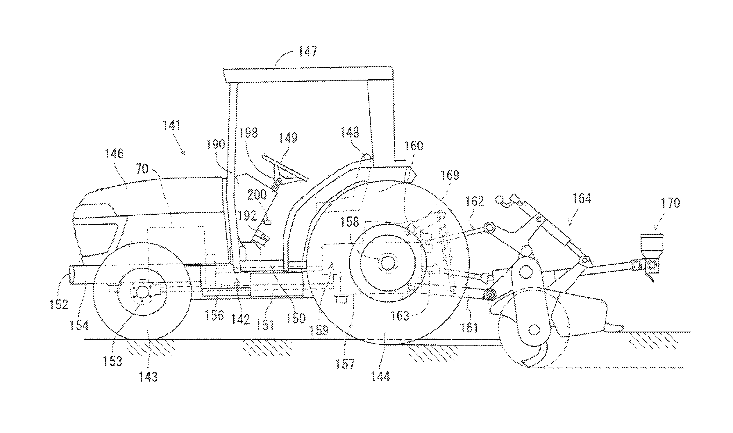
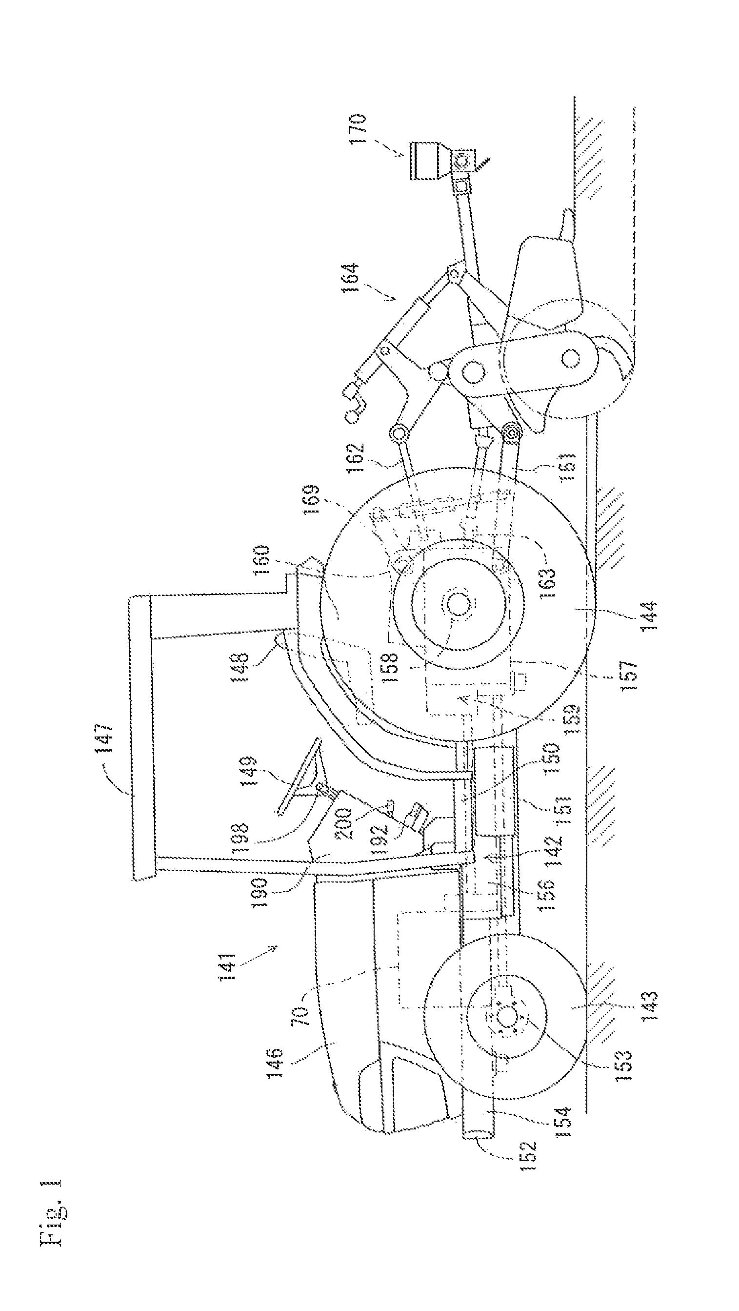
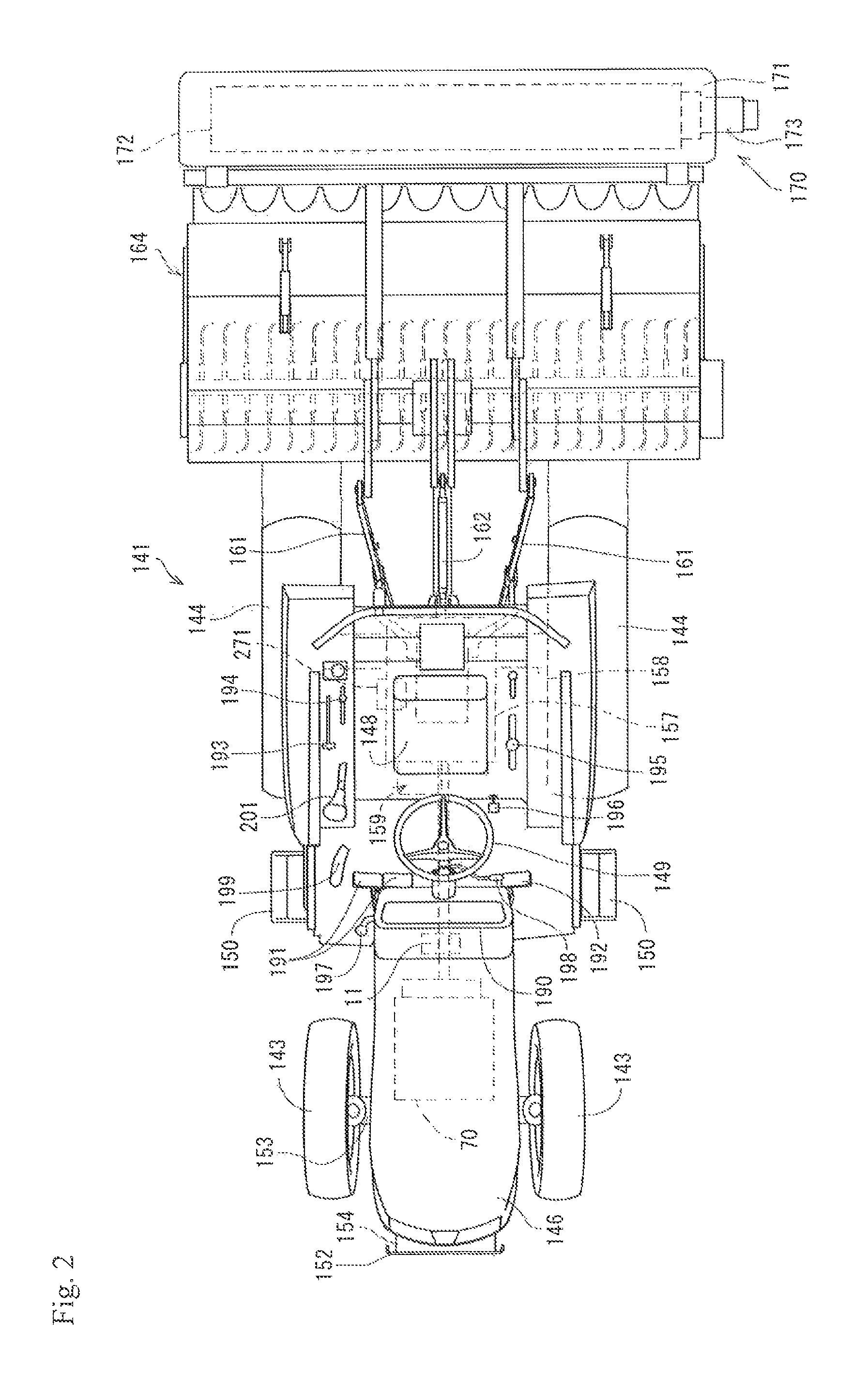
[0029]First of all, a description will be given of an outline structure of a tractor 141 corresponding to one example of a working vehicle with reference to FIGS. 1 and 2. As shown in FIGS. 1 and 2, a travel machine body 142 of the tractor 141 is supported by a pair of right and left front wheels 143 and a pair of right and left rear wheels 144. The tractor 141 is structured such as to travel forward and backward by driving the rear wheels 144 and the front wheels 143 by an engine 70 which is mounted to a front portion of the travel machine body 142. The engine 70 is covered with a hood 146. Further, a cabin 147 is installed to an upper surface of the travel machine body 142. A control seat 148 and a control steering wheel 149 moving a steering direction of the front wheels 143 right and left by a steering operation a...


PUM


Abstract

In a working vehicle, there is dissolved a risk that a black smoke is discharged, a knocking is generated and an engine stall is caused, if a lot of load is applied to a rotary tiller during various works while traveling at a low speed. In the working vehicle provided with an engine which is mounted to a travel machine body, a common rail type fuel injection device which injects fuel to the engine, and a continuously variable transmission which shifts power from the engine, an engine driving point Q (Q1→Q2) relating to a rotating speed N and a torque T of the engine is changed in such a manner that the rotation speed come to a high speed side rotating speed N2 dissolving an overload, and a change gear ratio of the continuously variable transmission is modified and regulates in such a manner that a vehicle speed V of the travel machine body does not change in the case that the overload acts on the engine of having a low speed N1 in the rotating speed N.

Description

TECHNICAL FIELD[0001]The present invention relates to a drive system (engine and continuously variable transmission) control device for a working vehicle, for example, an agricultural machine and a construction machine.BACKGROUND OF THE INVENTION[0002]Conventionally, a tractor corresponding to one example of the working vehicle has been provided with a travel machine body to which an engine and a transmission case are mounted, and a ground working machine such as a rotary tiller or the like which is installed to a rear portion of the travel machine body via a link mechanism so as to be movable up and down. A part of a rotary power transmitted from the engine to the transmission case is transmitted to the ground working machine via a PTO shaft which is provided in a protruding manner in the transmission case, and the ground working machine executes a predetermined work, for example, a plowing-up and tilling work (refer, for example, to patent document 1).[0003]In this kind of tractor...

Claims


Application Information

Patent Timeline
Patent Type & Authority Patents(United States)
IPC IPC(8): G06F7/70B60W10/06B60W10/101B60W10/30B60W30/188F02D29/00F16H47/02
CPCB60W10/06B60W30/1886B60W30/1882F02D29/00B60W10/30B60W30/1884F16H47/02B60W10/101B60W2510/0657B60W2720/10B60W2510/0638B60Y2200/221B60W2710/1005B60W2510/305Y10T477/619B60W10/103
Inventor OOUCHIDA, TAKESHIYUZAKI, KEIICHIROUKURODA, AKIFUMIHIRAI, TADAOIWAKI, KOJISAKATA, KOJIKAMADA, MINORU
Owner YANMAR POWER TECHNOLOGY CO LTD
Why Eureka
Try Eureka