Aircraft spring assembly

a technology for aircraft and springs, applied in the direction of spring motors, low internal friction springs, alighting gears, etc., can solve the problems of spring fatigue, particularly affected springs, and particularly problematic waves, and achieve the effect of reducing the amplitude of mechanical waves

Active Publication Date: 2016-12-01
MESSIER DOWTY
View PDF0 Cites 11 Cited by
  • Summary
  • Abstract
  • Description
  • Claims
  • Application Information

AI Technical Summary

Benefits of technology

[0013]an integral damping member provided within the load path between the load bearing surface of the coupling formation and the end region of the sprin

Problems solved by technology

Such springs are particularly affected by vibrational input.
The inventors have found that such waves c

Method used


Image

  • Aircraft spring assembly
  • Aircraft spring assembly
  • Aircraft spring assembly

Examples


Embodiment Construction

)

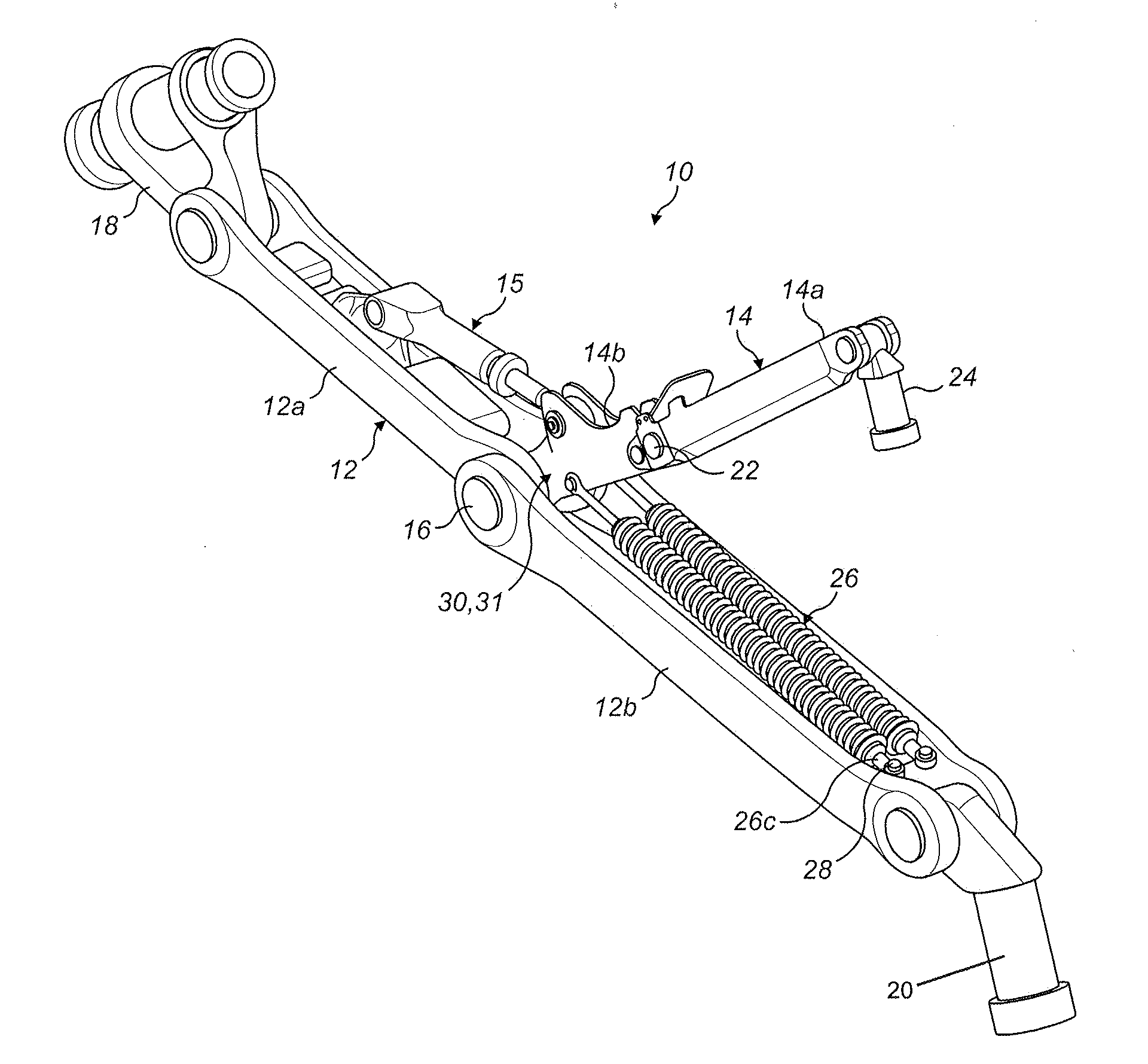
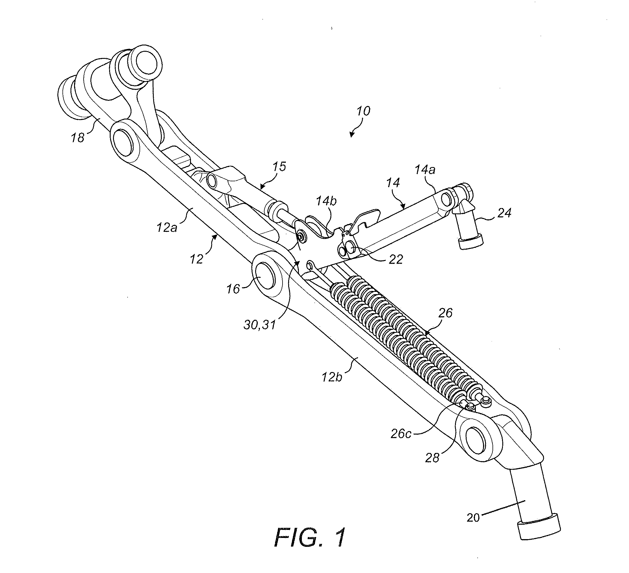
[0038]FIG. 1 shows a landing gear assembly 10 according to an embodiment of the invention. The landing gear assembly 10 includes of a conventional foldable stay 12, a conventional lock link 14, and aircraft spring assemblies 26 according to an embodiment of the invention serving as down-lock springs.

[0039]The stay 12 is arranged to be moved between a folded condition, in which the landing gear assembly 10 is stowed, and generally straight condition, in which the landing gear assembly 10 is deployed. The stay 12 has an elongate upper stay arm 12a having a lower end defining a pair of lugs pivotally coupled via a pivot pin 16 to a pair of lugs defined at an upper end of an elongate lower stay arm 12b. The stay arms 12a, 12b may therefore pivotally move relative to one another about the pivot pin 16. The upper end of the upper stay arm 12a defines a pair of lugs that are pivotally coupled to a lug of a connector 18 which in turn is pivotally coupled to the airframe (not shown). The lo...


PUM


Abstract

An aircraft spring assembly having a spring, an end fitting including a spring engagement formation arranged to be mechanically coupled to an end region of the spring and a coupling formation for coupling the spring assembly to an aircraft anchor point. The coupling formation includes a load bearing surface via which loads from the anchor point can be transmitted into the spring assembly. The assembly further includes an integral damping member provided within the load path between the load bearing surface of the coupling formation and the end region of the spring.

Description

[0001]This Application claims priority to and the benefit of European Application 15170170.3, filed on Jun. 1, 2015, which is incorporated herein by reference in its entirety.BACKGROUND OF THE INVENTION[0002]An aircraft spring assembly is a spring assembly arranged to be included as part of an aircraft assembly.[0003]One example of an aircraft assembly is an aircraft landing gear assembly. An aircraft landing gear assembly is generally movable between a deployed condition, for take-off and landing, and a stowed condition for flight.[0004]An actuator may be provided for moving the landing gear assembly between the deployed and stowed conditions. This type of actuator is known in the art as a “retraction actuator”. A retraction actuator may have one end coupled to the airframe and another end coupled to the main strut such that extension and retraction of the actuator results in movement of the main strut between deployed and stowed conditions.[0005]One or more stay assemblies may be ...

Claims


Application Information

Patent Timeline
IPC IPC(8): B64C25/20F16F3/10F03G1/10F16F3/04
CPCB64C25/20F03G1/10F16F3/10F16F3/04B64C25/26B64C25/62B64C25/64
Inventor VATOVEC, ANDRAZGREENWOOD, PAULPADDOCK, ANDREW
Owner MESSIER DOWTY
Why Eureka
Try Eureka