Network management method and apparatus
- Summary
- Abstract
- Description
- Claims
- Application Information
AI Technical Summary
Benefits of technology
Problems solved by technology
Method used
Image
Examples
first exemplary embodiment
1. First Exemplary Embodiment
1.1) System Architecture
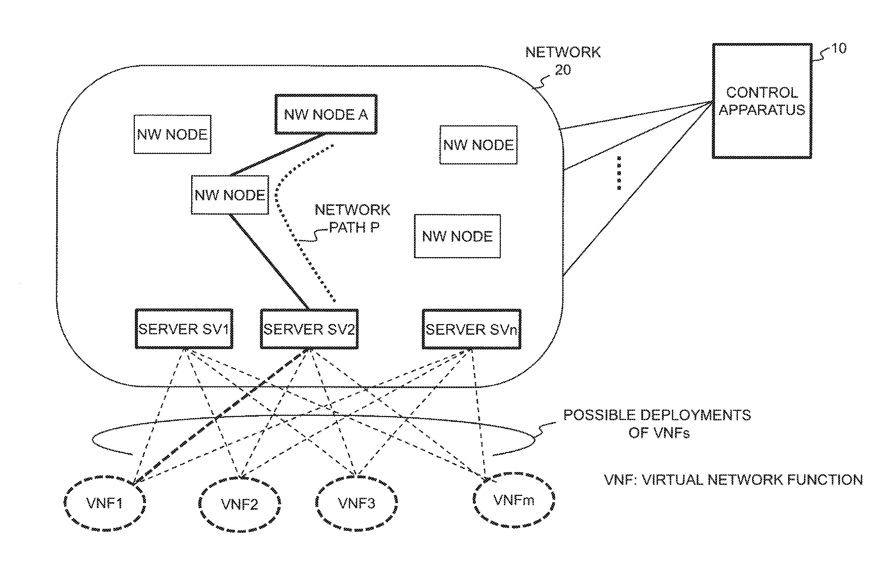
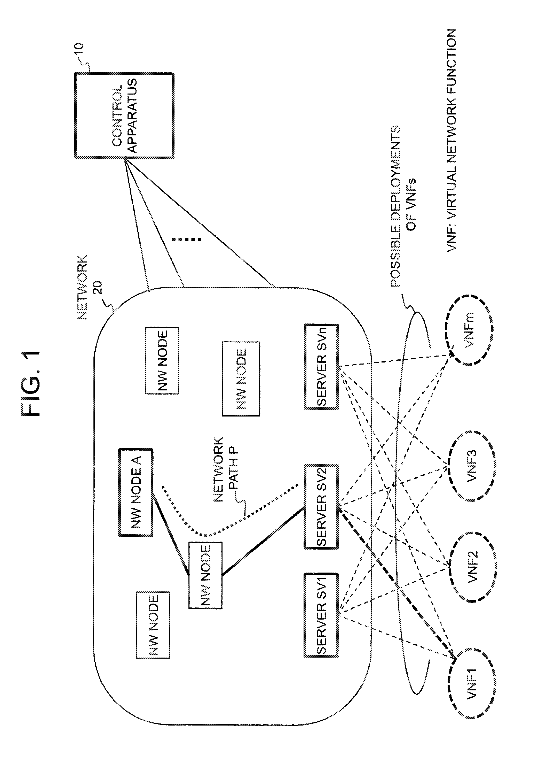
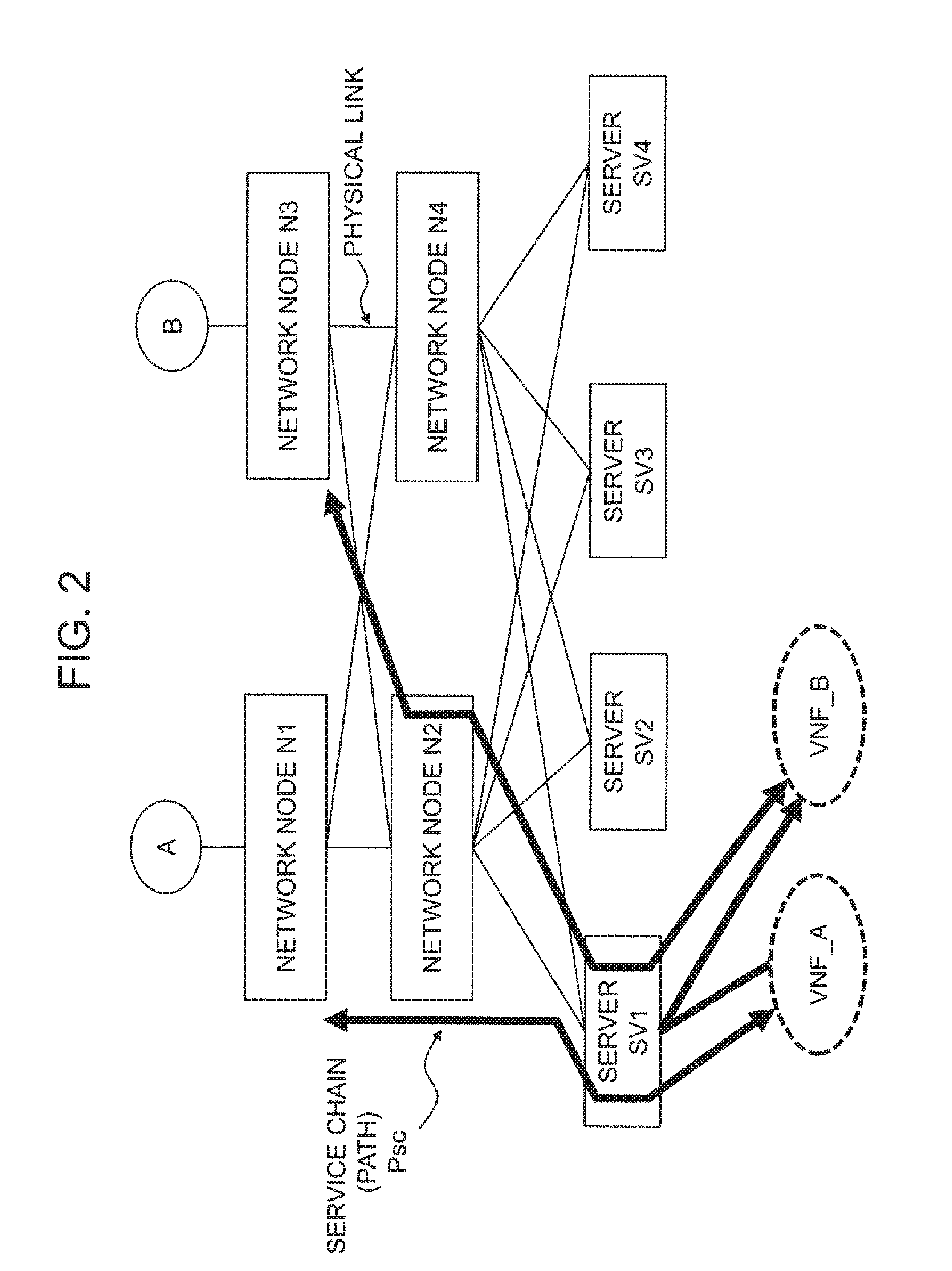
[0053]Referring to FIG. 3, a control apparatus 10 according to a first exemplary embodiment of the present invention includes a database 111 and a path determination section 112 and controls nodes N1 to N4 and servers SV1 to SV4 in a network 20. The path determination section 112 collectively performs VNF deployment onto servers and the configuration of a network path corresponding to a service chain. The database 111 includes information for the path determination section 112 to perform the above-described operation, which will be described later (see FIG. 5). Note that the control apparatus 10 has functions (not shown) of collecting under-mentioned information from the nodes, servers and the like in the network 20 and constructing the database 111.
[0054]Referring to FIG. 4, in each server SV, it is possible to configure a plurality of virtual machines VM1, VM2, . . . that perform a plurality of VNFs, respectively. In the present...
second exemplary embodiment
2. Second Exemplary Embodiment
[0061]A control apparatus 10 according to a second exemplary embodiment of the present invention determines a path for a service chain on a network that fulfills requirements, based on a result of comparison related to network condition and a result of comparison related to computing condition. Hereinafter, the second exemplary embodiment will be described in detail with reference to FIGS. 7 to 12.
2.1) System Architecture
[0062]Referring to FIG. 7, the control apparatus 10 according to the second exemplary embodiment of the present invention includes a database 111 and a path determination section 122 and, as in the case of the first exemplary embodiment, further has functions of collecting information from network nodes and the like and constructing the database 111. The database 111 is similar to that of the first exemplary embodiment and stores information for the path determination section 122 to perform path determination operation as shown in FIG. ...
third exemplary embodiment
3. Third Exemplary Embodiment
[0075]Referring to FIG. 13, in a network system according to a third exemplary embodiment of the present invention, an operation and management apparatus 30 can display various settings on a control apparatus 10 and a determined communication path for a service chain. The other configurations and functions are similar to those of the above-described first or second exemplary embodiment, and therefore a description thereof will be omitted, using the same reference signs as in FIG. 1. Note that the control apparatus 10 may be provided within the operation and management apparatus 30.
3.1) Operation and Management Apparatus
[0076]Referring to FIG. 14, the operation and management apparatus 30 includes a virtual link setting section 301, a requirement setting section 302, an interface 303 and a user interface 304 and, apart from them, also includes a control section and a storage section (not shown). The user interface 304 includes an information input section...
PUM
 Abstract
Description
Claims
Application Information
 - R&D
- Intellectual Property
- Life Sciences
- Materials
- Tech Scout
- Unparalleled Data Quality
- Higher Quality Content
- 60% Fewer Hallucinations
Browse by: Latest US Patents, China's latest patents, Technical Efficacy Thesaurus, Application Domain, Technology Topic, Popular Technical Reports.
© 2025 PatSnap. All rights reserved.Legal|Privacy policy|Modern Slavery Act Transparency Statement|Sitemap|About US| Contact US: help@patsnap.com


