Motor Vehicle Brake, In Particular A Motor Vehicle Brake That Can Be Actuated In A Combined Hydraulic And Electromechanical Manner, Comprising A Multi-Stage Spindle

a technology of motor vehicles and brakes, which is applied in the direction of brake systems, mechanical devices, transportation and packaging, etc., can solve the problems of elapsed significant amount of time, difficult to achieve the desired clamping action, and take a long time to achieve the desired clamping effect, and achieve the effect of high brake application for

Active Publication Date: 2016-12-08
LUCAS AUTOMOTIVE GMBH
View PDF3 Cites 20 Cited by
  • Summary
  • Abstract
  • Description
  • Claims
  • Application Information

AI Technical Summary

Benefits of technology

[0006]A feature of the present invention is to provide a motor vehicle brake that can be actuated in a combined hydraulic and electromechanical manner, which may be utilized as a service brake as well as a parking brake, and which, with a simple design and also using a relatively low-power electric motor drive, allows a reduction in the time for achieving the desired clamping action.
[0014]The compression spring mechanism causes the two nut sections to be stretched, i.e., spread, apart from one another. If the spindle associated with the second nuts, with their two nut sections, and their thread are viewed in the axial direction, the internal thread of the first nut section is pressed by the compression spring mechanism against thread flanks of the spindle leading in the viewing direction, whereas the internal thread of the second nut section is pressed against differently oriented, i.e., trailing, thread flanks of the spindle. The compression spring mechanism is correspondingly pretensioned, and thus ensures relatively high static friction between the two nut sections and the spindle associated therewith. The two nut sections are braced, so to speak, on the spindle by the compression spring mechanism and the axial force which it exerts, similarly as for two mutually locked nuts. As a result, in this braced state a relative rotation of the second nut, comprising the two nut sections, relative to the spindle is much more difficult, as a function of the magnitude of the axial force exerted by the compression spring mechanism. In contrast, a relative rotation between the first spindle and the first nut associated therewith is much easier, i.e., has much lower resistance.
[0016]Relatively high clamping forces may be achieved in the desired area via the second spindle-nut pair which has the relatively small thread pitch. In contrast, the first spindle-nut pair brings about a rapid displacement of the actuating element, and thus of the brake lining, for quickly passing through the clearance.
[0019]One refinement of the invention provides that the first spindle of the first spindle-nut pair is coupled in a rotatably fixed manner to the second nut section of the second nut of the second spindle-nut pair, or is formed in one piece with same. It is thus possible to cost-effectively design the first spindle and the second nut section of the second nut as an integral part.
[0021]One refinement of the invention provides that a preferably multi-stage gear system, situated between the motor drive and the spindle-nut arrangement, is associated with the displacement mechanism. This makes it possible to provide a relatively low-power motor drive and still achieve high brake application forces in the area of the spindle-nut arrangement via a suitable gear system having an adequate gear ratio.

Problems solved by technology

One disadvantage of this motor vehicle brake is that during an electromechanical actuation, a relatively large actuating travel must be overcome, which may take a very long time until the desired clamping action with the desired brake force is achieved.
In addition, this design is relatively complicated.
Here as well, this motor vehicle brake has the disadvantage that a significant amount of time may elapse before the desired clamping action is achieved.

Method used


Image

  • Motor Vehicle Brake, In Particular A Motor Vehicle Brake That Can Be Actuated In A Combined Hydraulic And Electromechanical Manner, Comprising A Multi-Stage Spindle
  • Motor Vehicle Brake, In Particular A Motor Vehicle Brake That Can Be Actuated In A Combined Hydraulic And Electromechanical Manner, Comprising A Multi-Stage Spindle
  • Motor Vehicle Brake, In Particular A Motor Vehicle Brake That Can Be Actuated In A Combined Hydraulic And Electromechanical Manner, Comprising A Multi-Stage Spindle

Examples


Embodiment Construction

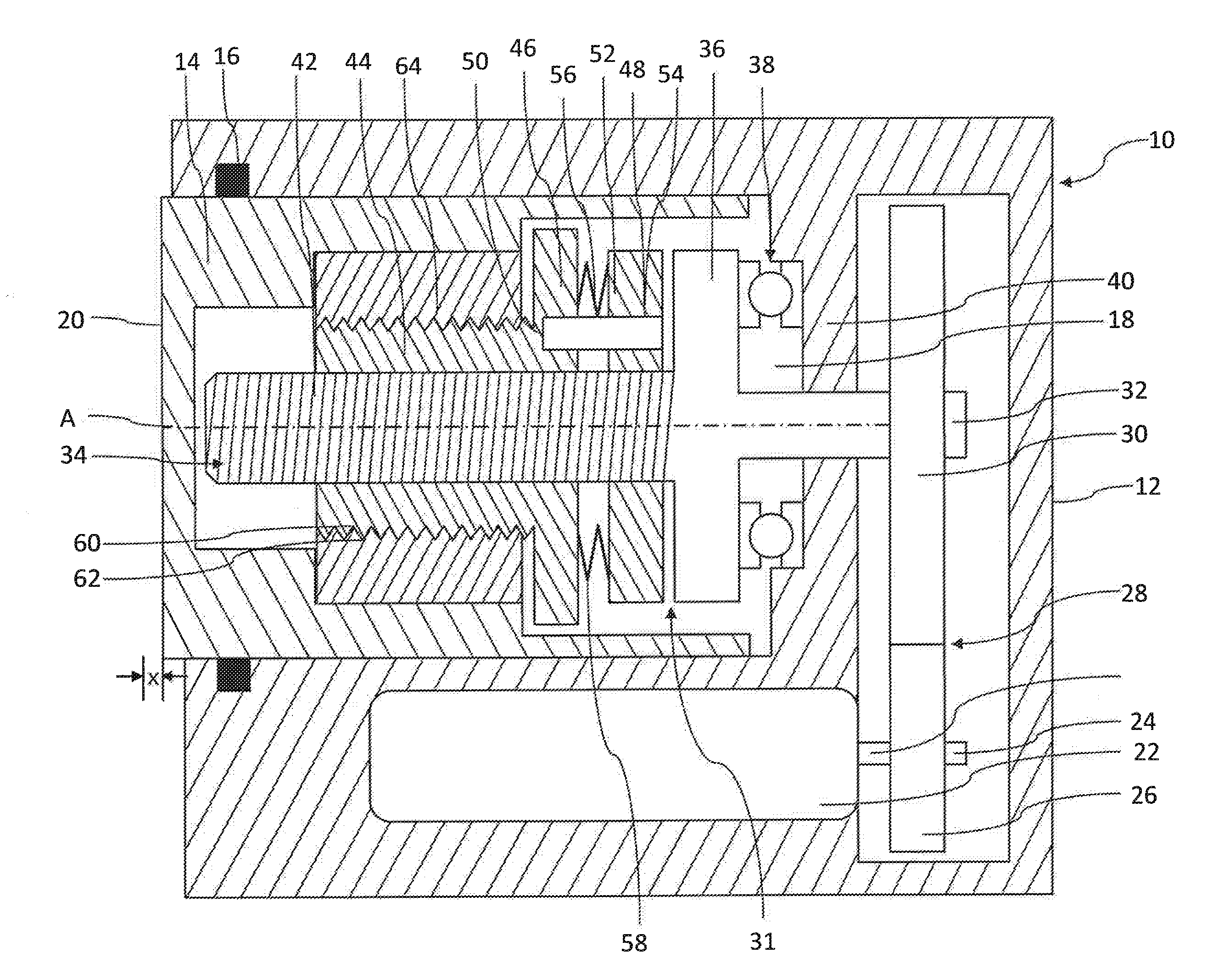
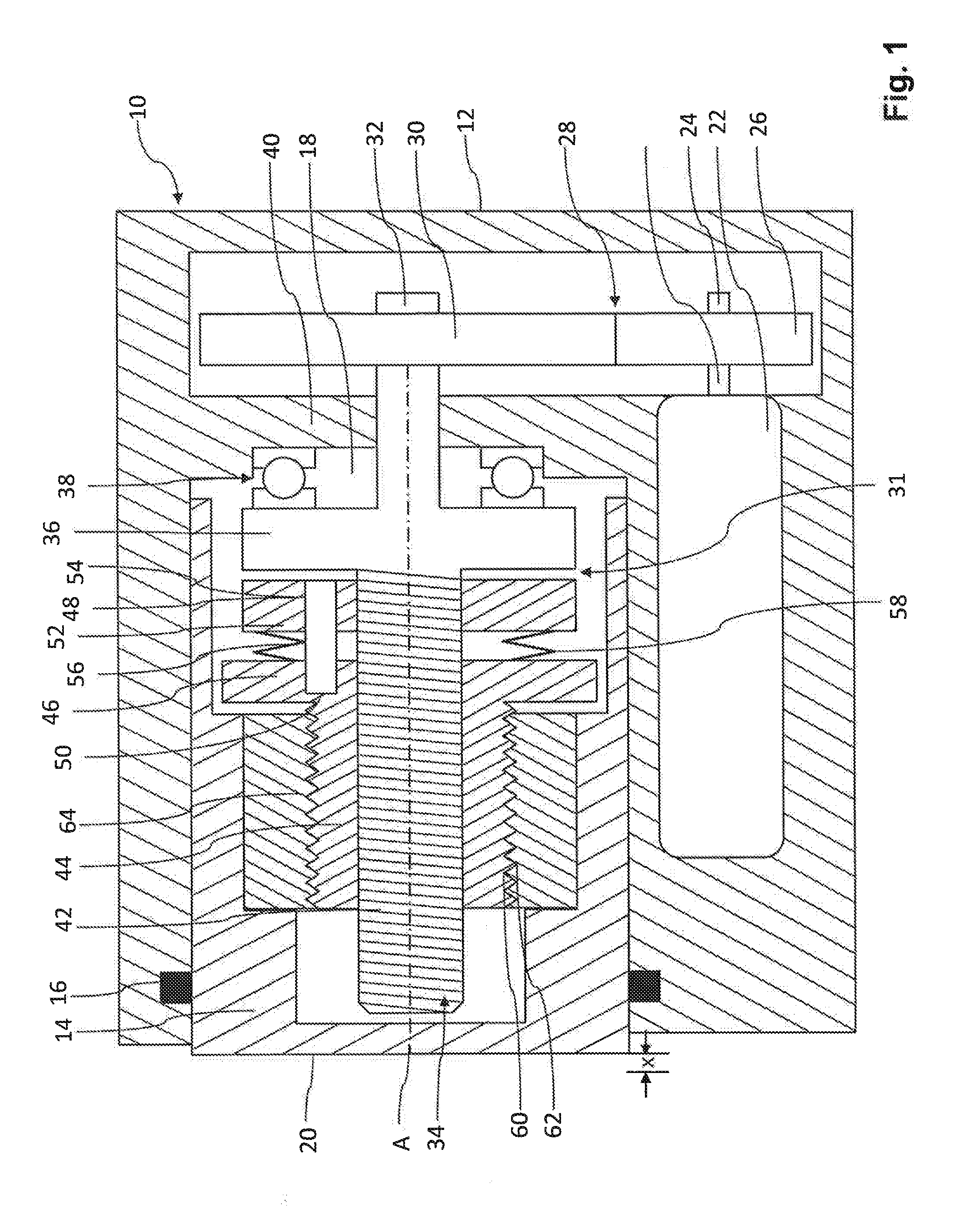
[0028]FIG. 1 shows a motor vehicle brake according to the invention, denoted in general by reference numeral 10. The motor vehicle brake includes a housing 12 in which an actuating element in the form of a hydraulic piston 14 and which is displaceable with respect to a longitudinal axis A is displaceably accommodated. The piston 14 is secured against rotation and is guided within the housing 12 via a fluid seal 16. The piston 14 may be displaced along the longitudinal axis A in a conventional manner by the action of brake fluid on a pressure chamber 18 in order to press a brake lining (not shown), coupled to an end face 20 of the piston 14, to a brake disc (likewise not shown) upon brake activation. The piston 14 returns to its starting position in the conventional manner due to release of the hydraulic fluid from the pressure chamber 18.

[0029]During actuation of the piston 14, the piston must initially be moved over a distance x which corresponds to a clearance that is present in t...


PUM


Abstract

The invention relates to a motor vehicle brake, in particular a motor vehicle brake that can be actuated in a combined hydraulic and electromechanical manner, having an actuator assembly comprising: a housing, an actuating element that can be displaced relative to the housing along a longitudinal axis for the hydraulic or electromechanical displacement of a brake lining, a motor drive, and a displacement mechanism, arranged between the motor drive and the displaceable actuating element, for displacing the actuating element. The displacement mechanism has a multi-stage spindle-nut arrangement comprising a first spindle-nut pair having a first thread pitch and a second spindle-nut pair having a second thread pitch, wherein the first thread pitch is greater than the second thread pitch, wherein, during an electromechanical actuation of the motor vehicle brake, the first spindle-nut pair is active in a first actuating phase and the second spindle-nut pair is active in a second actuating phase.

Description

CROSS-REFERENCE TO RELATED APPLICATIONS[0001]This application is a national stage of International Application No. PCT / EP2015 / 053253 filed 17 Feb. 2015, the disclosures of which are incorporated herein by reference in entirety, and which claimed priority to German Patent Application No. 10 2014 002 484.9 filed 19 Feb. 2014, the disclosures of which are incorporated herein by reference in entirety.BACKGROUND OF THE INVENTION[0002]The present invention relates to a motor vehicle brake, in particular a motor vehicle brake that can be actuated in a combined hydraulic and electromechanical manner, having an actuator assembly comprising: a housing, an actuating element that is displaceable relative to the housing along a longitudinal axis for the hydraulic or electromechanical displacement of a brake lining, a motor drive, and a displacement mechanism, situated between the motor drive and the displaceable actuating element, for displacing the actuating element.[0003]Motor vehicle brakes o...

Claims


Application Information

Patent Timeline
Patent Type & Authority Applications(United States)
IPC IPC(8): B60T13/74F16D65/18
CPCB60T13/741F16D65/18F16D2121/04F16D2125/48F16D2125/405F16D2123/00F16D2121/24F16D2125/40
Inventor OHLIG, BENEDIKTMICHELS, ERWIN
Owner LUCAS AUTOMOTIVE GMBH
Why Eureka
Try Eureka