
Power supply apparatus with cable voltage drop compensation

a technology of power supply apparatus and voltage drop compensation, which is applied in the direction of power conversion systems, dc-dc conversion, instruments, etc., can solve the problems of reducing the reliability of the power cable, the impedance of the circuit of the power cable itself or the plug of the power cable will generate a noticeable voltage drop, and the power cable itself usually has impedance, so as to enhance the stability of the voltage of the load terminal

Active Publication Date: 2016-12-08
ACER INC
View PDF4 Cites 13 Cited by
  • Summary
  • Abstract
  • Description
  • Claims
  • Application Information

AI Technical Summary

Benefits of technology

The patent text describes a power supply apparatus that uses a compensation circuit to detect the output voltage and generate a compensation voltage to compensate for voltage drops in the output voltage. As a result, the stability of the load voltage is enhanced, and the problem of sudden voltage drops due to high load can be improved. The power supply apparatus does not require an additional sensing wire, which increases reliability and reduces cost and size of the wire.

Problems solved by technology

However, a power cable itself usually has impedance.
When the load increases such that the current passing through the power cables become large, the impedance of the circuit of the power cable itself or the plug of the power cable will generate a noticeable voltage drop.
However, the additional sensing wire may reduce the reliability of the power cable and increase cost of the power cable.
Therefore, under the premise of not adopting an additional sensing wire, how to lower the influence the voltage drop on the power cables has on the voltage at the load terminal such that the stability of the voltage at the load terminal may be enhanced is still an issue which a person skilled in the art is faced with.

Method used


Image

  • Power supply apparatus with cable voltage drop compensation
  • Power supply apparatus with cable voltage drop compensation
  • Power supply apparatus with cable voltage drop compensation

Examples


Embodiment Construction

[0016]Reference will now be made in detail to the present preferred embodiments of the disclosure, examples of which are illustrated in the accompanying drawings. Wherever possible, the same reference numbers are used in the drawings and the description to refer to the same or like parts.

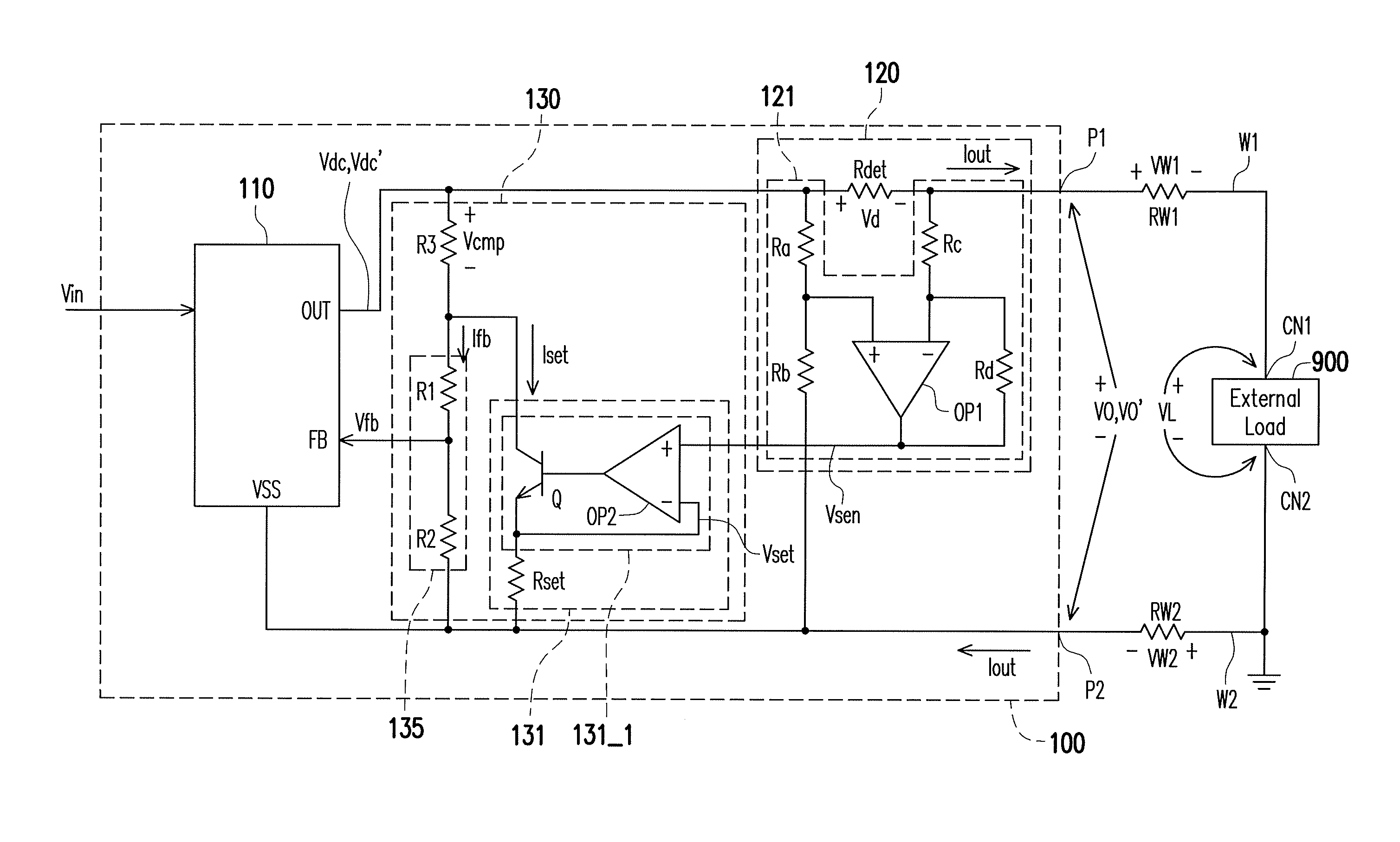
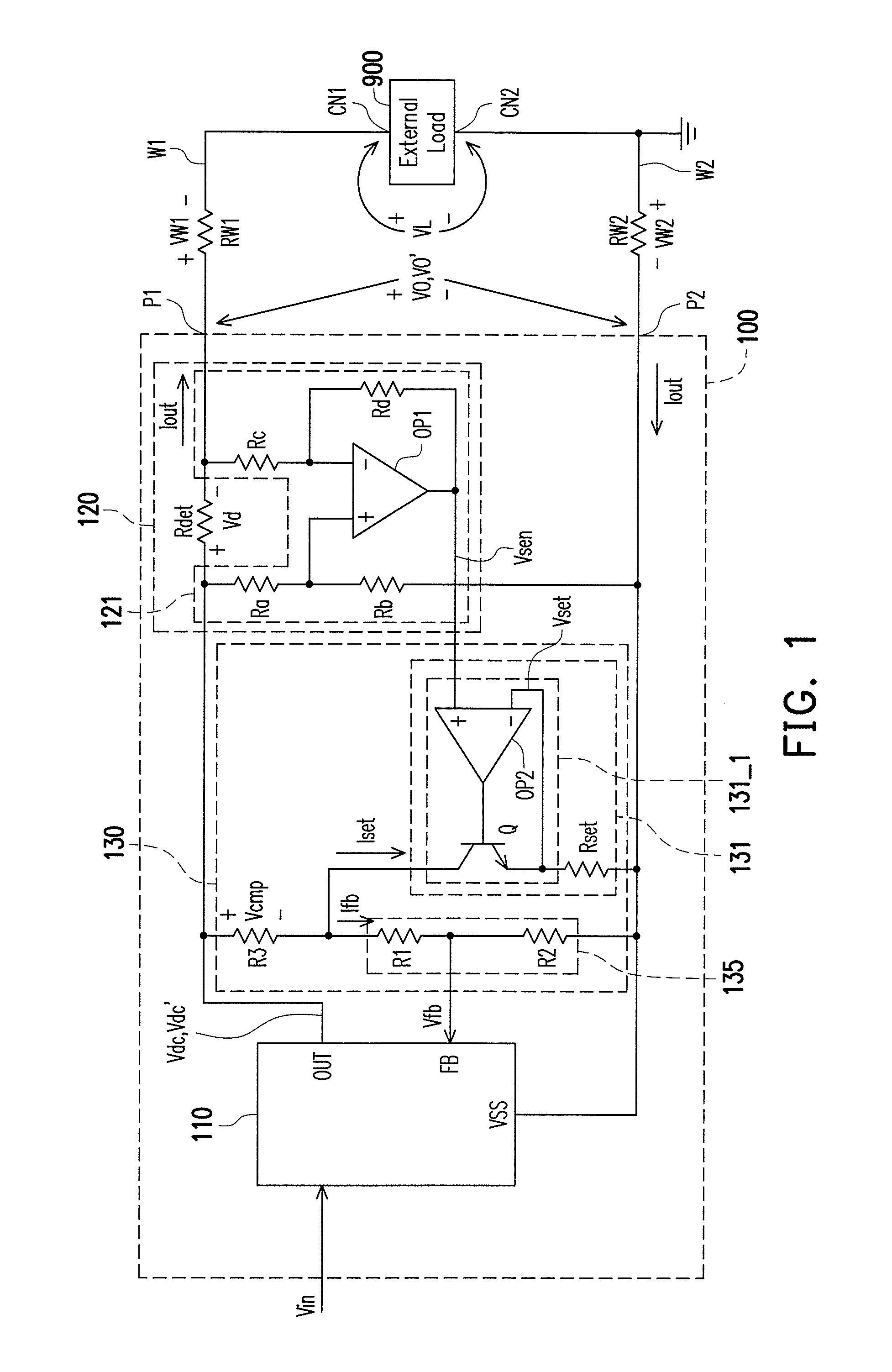
[0017]Referring to FIG. 1, FIG. 1 illustrates a power supply apparatus 100 with cable voltage drop compensation according to an embodiment of the disclosure. As shown in FIG. 1, the power supply apparatus 100 may supply power to an external load 900. The external load 900 may be, for example, a cell phone, a tablet PC, a notebook computer, a portable power supply and such electronic device, however the disclosure is not limited thereto. The power supply apparatus 100 may include a first power pin P1, a second power pin P2, a direct current (DC) output regulator 110, a current sensing circuit 120 and a compensation circuit 130, however the disclosure is not limited thereto. The first power pin P1 and...


PUM


Abstract

A power supply apparatus is provided. The power supply apparatus includes a first power pin, a second power pin, a DC output regulator, a current sensing circuit, and a compensation circuit. The first and second power pins are coupled to an external load through a first wire and a second wire respectively. The DC output regulator receives an input voltage and a feedback voltage and generates an output voltage and an output current. The current sensing circuit senses the output current and generates a sensing voltage. The compensation circuit generates a compensation voltage responding to the sensing voltage. The compensation voltage is a sum of a voltage drop on the first wire and a voltage drop on the second wire. The compensation circuit compensates the output voltage according to the compensation voltage, such that a load voltage of the external load is kept at a stable voltage value.

Description

CROSS-REFERENCE TO RELATED APPLICATION[0001]This application claims the priority benefit of Taiwan application serial no. 104118512, filed on Jun. 8, 2015. The entirety of the above-mentioned patent application is hereby incorporated by reference herein and made a part of this specification.BACKGROUND OF THE DISCLOSURE[0002]Field of the Disclosure[0003]The disclosure relates to a power supply apparatus, and relates particularly to a power supply apparatus with cable voltage drop compensation.[0004]Description of Related Art[0005]Typically, most power supply apparatuses are coupled to a load (for example, a cell phone, a table PC, a notebook computer, a portable power source and such electronic device) through a power cable, so as to supply power (or charge) to the load. However, a power cable itself usually has impedance. When the load increases such that the current passing through the power cables become large, the impedance of the circuit of the power cable itself or the plug of ...

Claims


Application Information

Patent Timeline
Patent Type & Authority Applications(United States)
IPC IPC(8): G05F1/56G05F1/565
CPCG05F1/565G05F1/561H02M3/156
Inventor LU, CHI-NAN
Owner ACER INC
Learn More