Device and method for controlling link actuation device

a technology of actuation device and control device, which is applied in the direction of manipulators, gearings, program-controlled manipulators, etc., can solve the problems of welding thickness unevenness, coating unevenness,

Active Publication Date: 2016-12-15
NTN CORP
View PDF0 Cites 12 Cited by
  • Summary
  • Abstract
  • Description
  • Claims
  • Application Information

AI Technical Summary

Benefits of technology

[0022]An object of the present invention is to solve the above problem and to provide a control device and a control method for a link actuation device that allow, when work is performed with an end effector by using a link actuation device that includes three or more quadric chain link mechanisms, the end effector to perform work while moving at a substantially constant speed on a work surface.

Problems solved by technology

Therefore, in a case where laser processing, coating by a dispenser or by ink jet, welding or the like is performed by using a link actuation device that includes three or more quadric chain link mechanisms shown in FIG. 9 and FIG. 10, if the end effector performs operation at an inconstant speed on the work surface, working unevenness, coating unevenness, thickness unevenness in welding or the like occurs.

Method used


Image

  • Device and method for controlling link actuation device
  • Device and method for controlling link actuation device
  • Device and method for controlling link actuation device

Examples


first embodiment

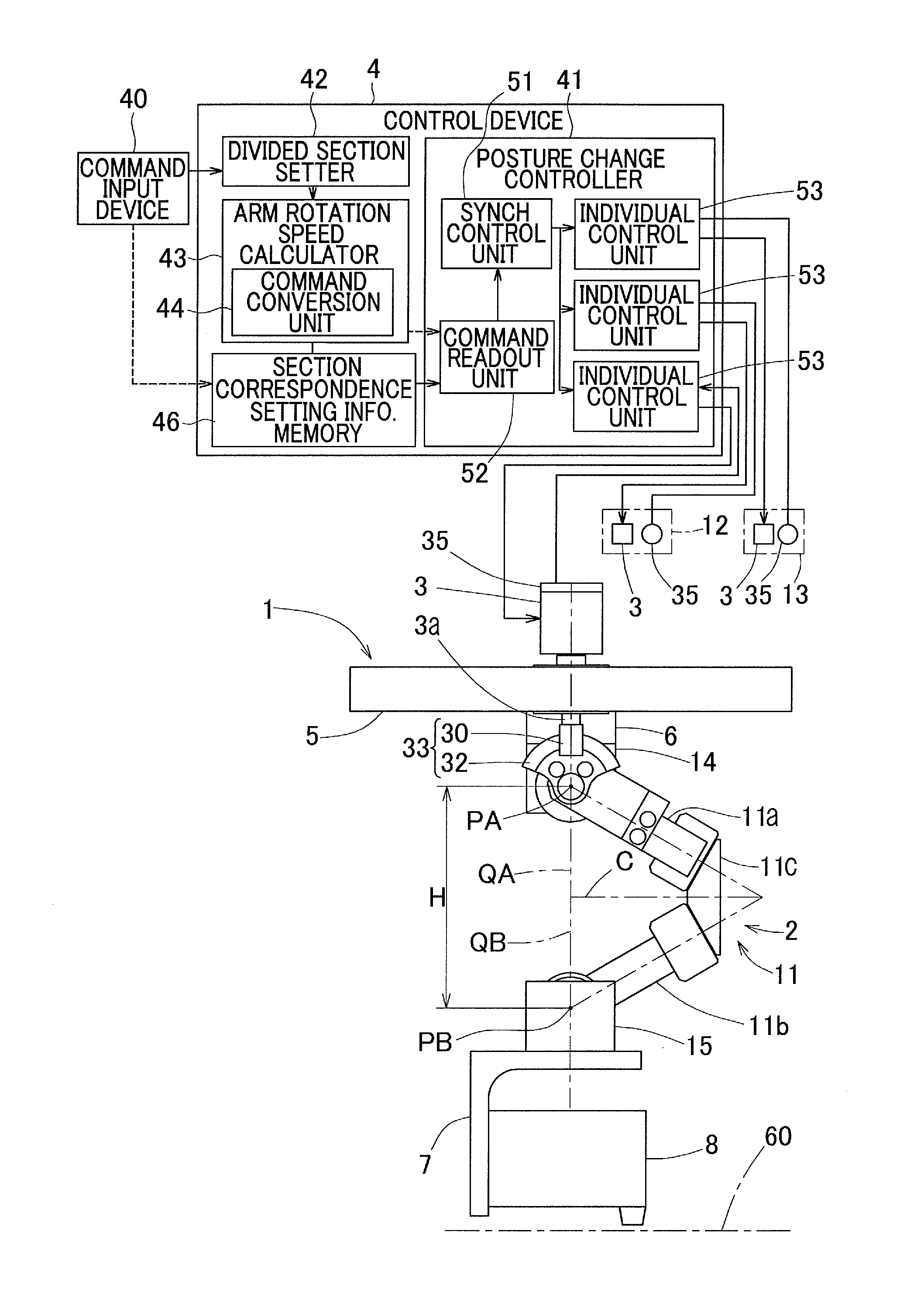
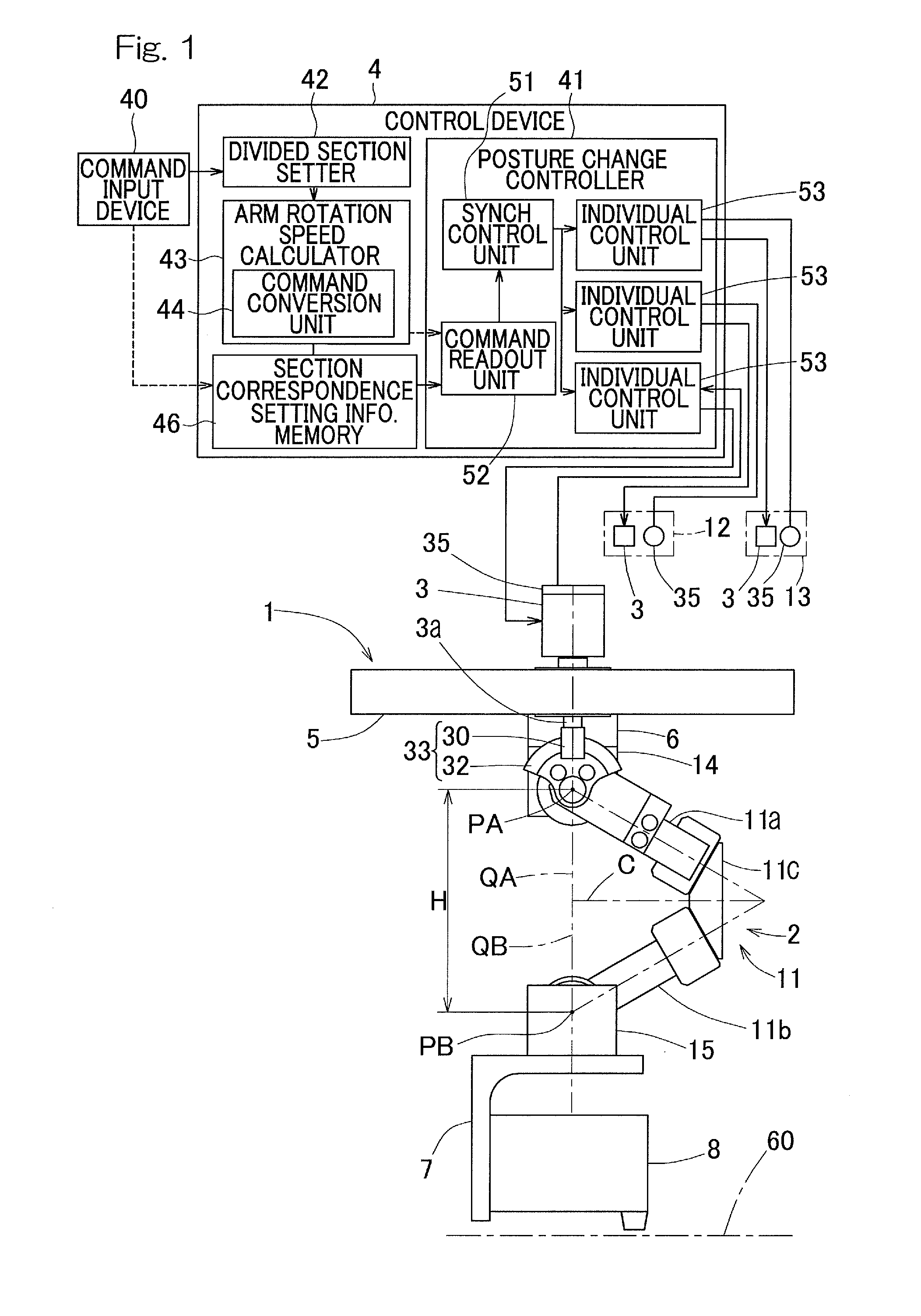
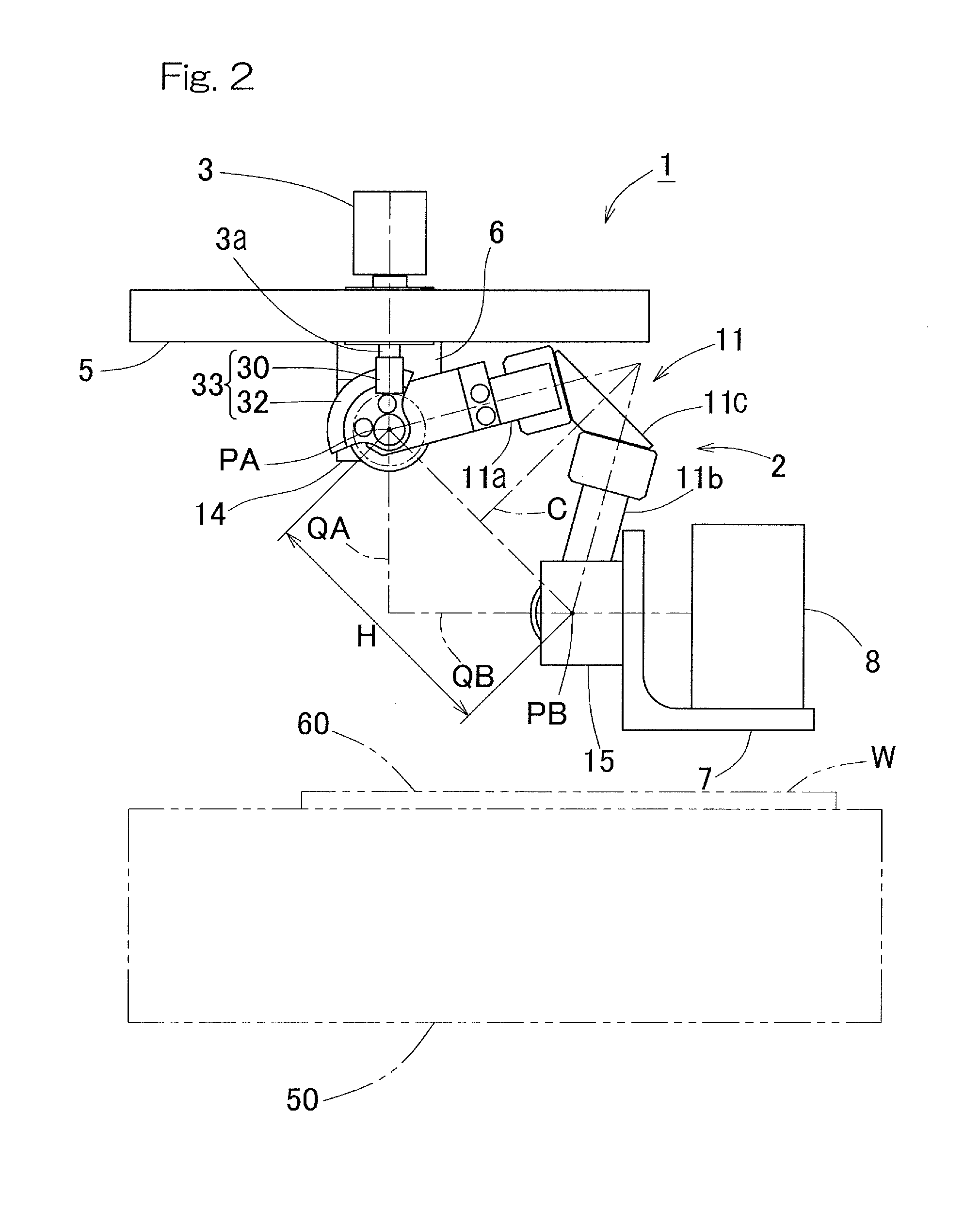
[0052]A control device and a control method for a link actuation device according to a first embodiment of the present invention will be described with reference to the drawings. First, the link actuation device to be controlled will be described with reference to FIG. 1 to FIG. 5. As shown in FIG. 1 and FIG. 2, this link actuation device 1 includes a link actuation device body 2 and a plurality of posture control actuators 3 which causes the link actuation device body 2 to actuate. These posture control actuators 3 are controlled by a control device 4. In the present embodiment, the link actuation device body 2 is installed in a suspended manner to a support member 5 via a spacer 6, on the proximal end side of the link actuation device body 2.

[0053]On the distal end side of the link actuation device body 2, an end effector 8 is mounted via a distal end mounting member 7. Each actuator 3 is a servomotor, for example, and includes a position detector 35. The end effector 8 is, for ex...

second embodiment

[0098]A second embodiment of the present invention will be described with reference to FIG. 8. The second embodiment is the same as the first embodiment except the features to be specifically described. In the second embodiment, the divided section setter 42, the arm rotation speed calculator 43, and the section correspondence setting information memory 46 shown in FIG. 1 have functions that are partially different from those in the first embodiment. With respect to the section correspondence setting information memory 46, the values to be stored are different from those in the first embodiment.

[0099]In the first embodiment, description has been given of the constant speed movement performed when the work surface 60 of the end effector 8 is a flat surface. However, also when the work surface 60 is a spherical surface, the operation of the distal end of the end effector 8 at this spherical work surface 60 can be made into a constant speed operation similarly to the above explanation....

third embodiment

[0107]A third embodiment of the present invention will be described. In the third embodiment, in a case where the table device 50 shown in FIG. 2 moves thereby causing the target work piece W to be moved relative to the end effector 8 of the link actuation device 1, the speed of this relative movement is made a constant speed. The table device 50 is an XY table whose table surface moves in two axial directions orthogonal to each other, and in FIG. 2, the target work piece W is moved whose surface serves as the work surface 60 being a flat surface. However, a configuration may be employed in which the link actuation device 1 is mounted on the table device 50 and the link actuation device 1 is moved, whereas the work piece W is fixed.

[0108]The third embodiment is the same as the first embodiment except the features to be specifically described. In the third embodiment, the divided section setter 42, the arm rotation speed calculation speed calculation means 43 and the section correspo...


PUM


Abstract

In this link actuation device, arms of a plurality of link mechanisms are driven to be rotated by actuators, whereby the posture of a distal end side link hub is changed. A divided section setter divides a trajectory on a work surface on which an end effector works, into a plurality of sections at pass points and sets the sections. An arm rotation speed calculator calculates a rotation speed at which each arm performs constant speed rotation in each section on the basis of: a time period of movement in the section which is determined from a target moving speed and the distance of the section; and a rotation-angular movement amount of the arm in the section. A posture change controller performs positioning control on each actuator so as to cause its corresponding arm to continuously rotate at the corresponding rotation speed without acceleration/deceleration.

Description

CROSS REFERENCE TO THE RELATED APPLICATION[0001]This application is a continuation application, under 35 U.S.C. §111(a) of international patent application No. PCT / JP2015 / 053739, filed Feb. 12, 2015, which claims priority to Japanese patent application No. 2014-030425, filed Feb. 20, 2014, the entire disclosure of which is herein incorporated by reference as a part of this application.BACKGROUND OF THE INVENTION[0002]Field of the Invention[0003]The present invention relates to a control device and a control method for a link actuation device to be used in an apparatus, such as an industrial apparatus, that requires a precise and wide operating range.[0004]Description of Related Art[0005]As link actuation devices that fast and precisely perform work such as complicated working or processing in a three-dimensional space, there are devices that each include three or more quadric chain link mechanisms to allow movement of two degrees of freedom (for example, Patent Documents 1 to 3 list...

Claims


Application Information

Patent Timeline
Patent Type & Authority Applications(United States)
IPC IPC(8): B25J9/16F16H21/46
CPCB25J9/1623B25J9/1651F16H21/46
Inventor SAKATA, SEIGONISHIO, YUKIHIROISOBE, HIROSHIYAMADA, HIROYUKI
Owner NTN CORP
Why Eureka
Try Eureka