
Angle bisector gauge

a technology of bisector and gauge, which is applied in the direction of measuring gauges, woodworking apparatus, manufacturing tools, etc., can solve the problems of many opportunities for error to creep into a process that requires precision, and the traditional methods used to form mitered joints oftentimes do not allow for acceptable, and the chance of inaccuracy in cutting the boards is increased

Inactive Publication Date: 2016-12-15
CLERC GREGORY A
View PDF12 Cites 9 Cited by
  • Summary
  • Abstract
  • Description
  • Claims
  • Application Information

AI Technical Summary

Benefits of technology

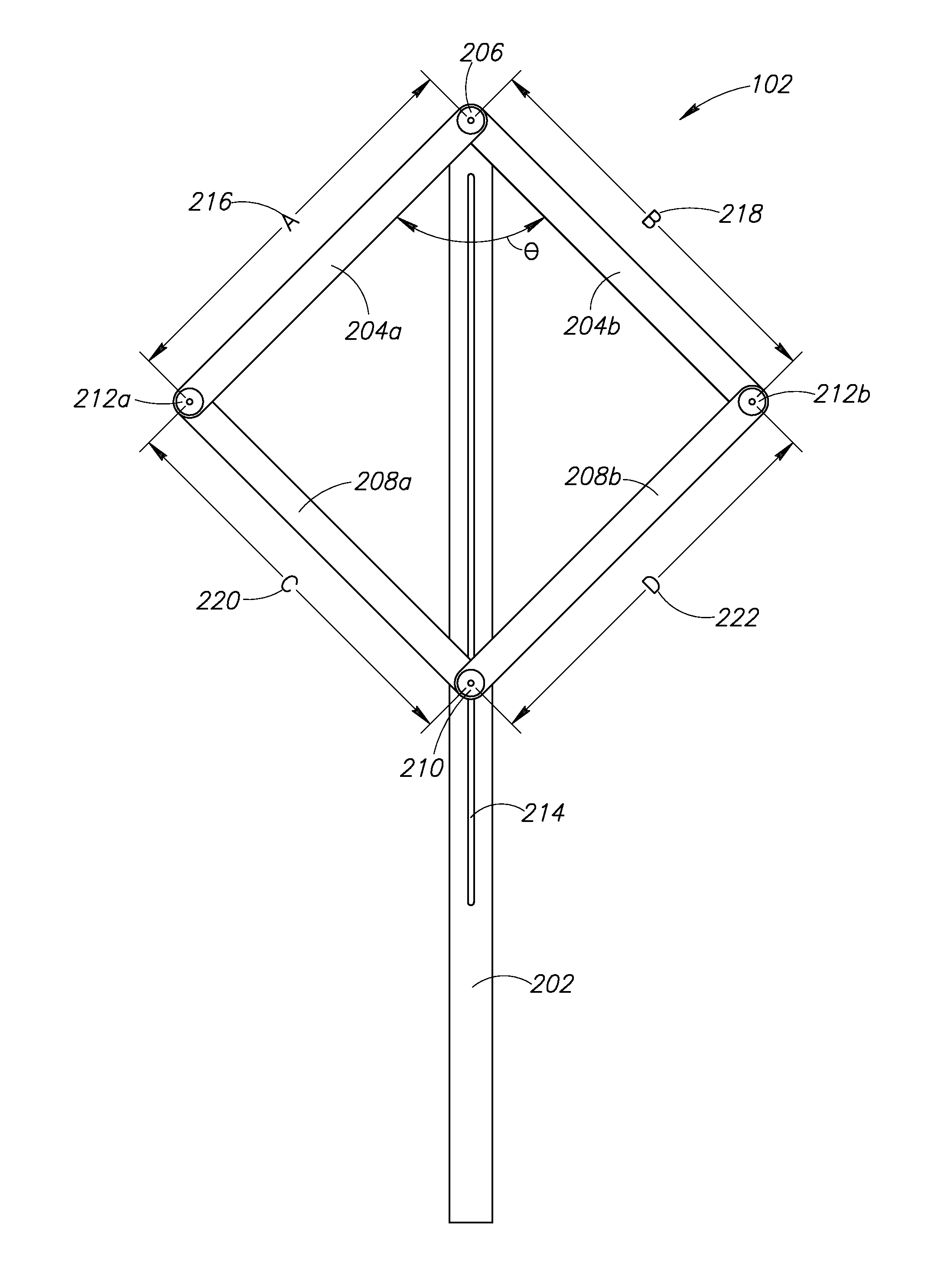
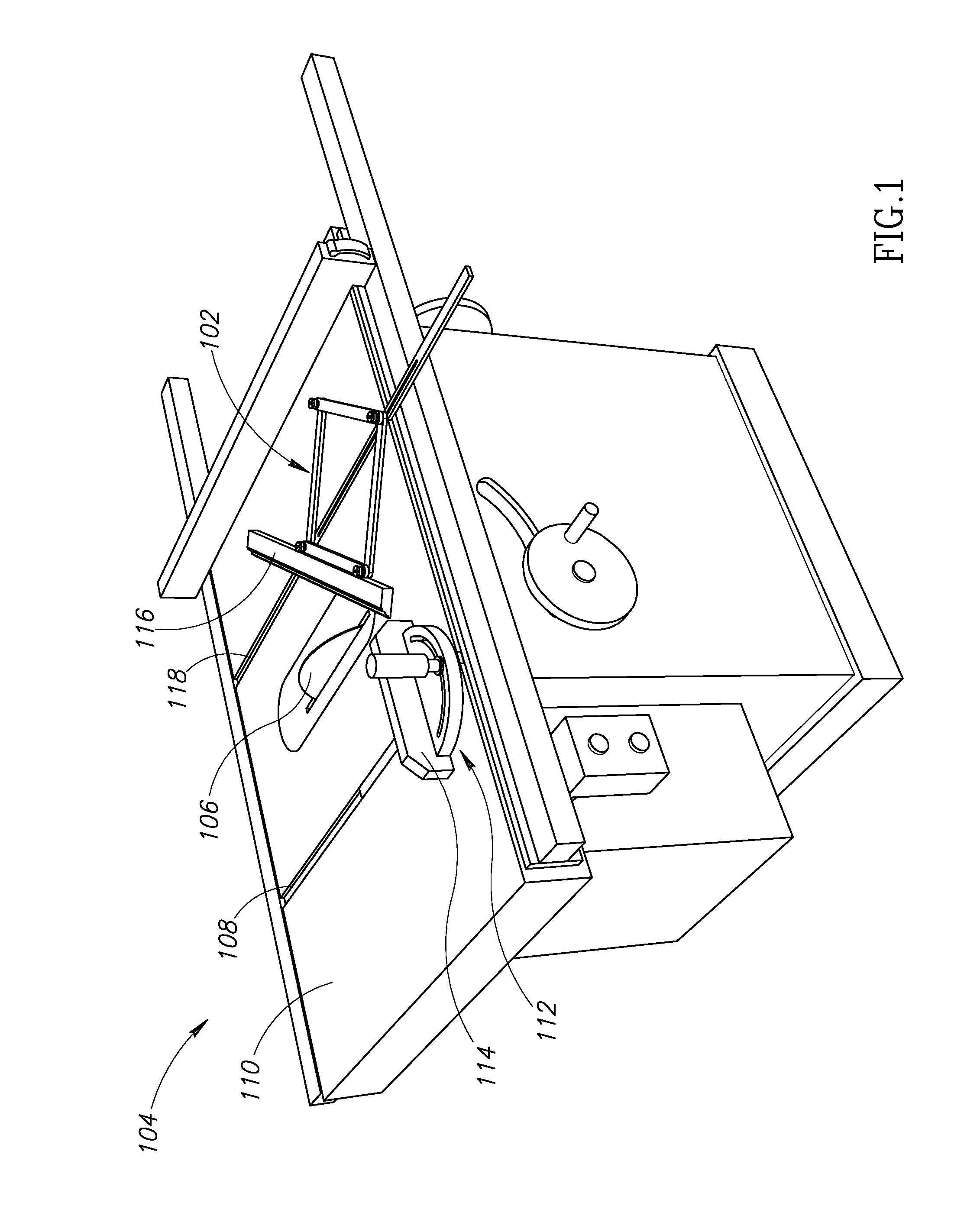
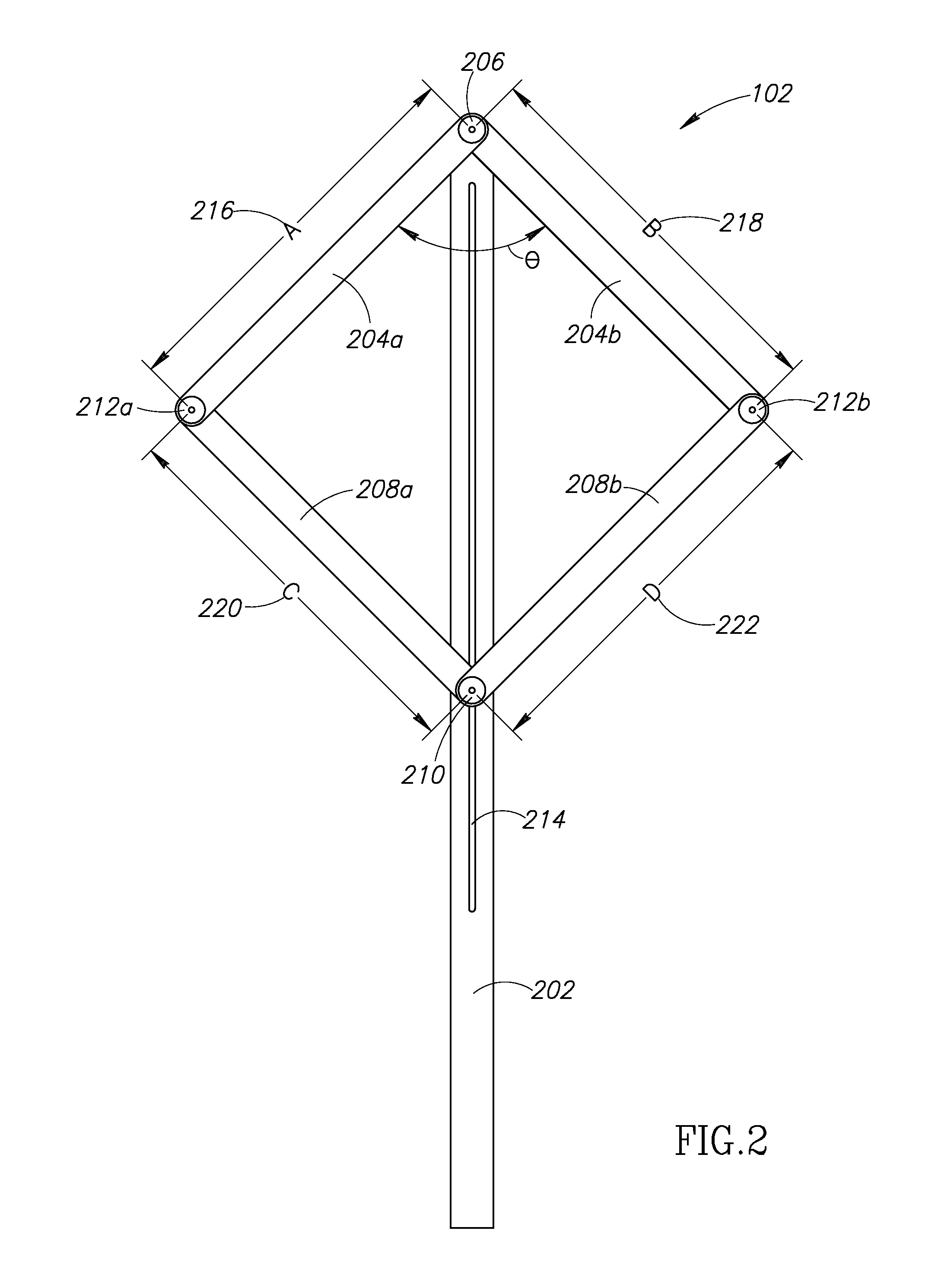
The patent describes an apparatus for measuring and creating miter joints on a table saw. The apparatus includes a guide bar with a slot and a pair of angle arms that can slide within the guide bar. The angle arms have a vertex end and a second end. A scale is displayed on the guide bar to show the angle formed by the angle arms. The apparatus also includes a threaded fastener and a retaining member to secure the guide bar in place. The apparatus can be used to measure and create miter joints on a table saw by aligning the angle arms with the blade and using a miter gauge. The patent also describes a quadrilateral formed by the angle arms and a kite-shaped scale on the guide bar to indicate the angle. The apparatus can be symmetrically aligned and has a symmetrical design.

Problems solved by technology

When making angled cuts on picture frames or trim boards to form a mitered joint, there are many opportunities for error to creep into a process that requires precision to achieve a pleasing result.
The traditional methods used to form mitered joints oftentimes do not allow for acceptable results without some trial and error.
This is due, in part, to the inaccuracy in the tools used to measure the corner, a chance for error when calculating the proper angle based on the measured corner, additional inaccuracy in setting up the saw or the gauge to the proper calculated angle, and an even further chance for inaccuracy when cutting the boards.
The problem is compounded in situations where many mitered joints are required to be used in combination to frame around an object, such as a picture frame or other multi-sided object.

Method used


Image

  • Angle bisector gauge
  • Angle bisector gauge
  • Angle bisector gauge

Examples


Embodiment Construction

[0024]In the fields of carpentry and woodworking, there arise many occasions where the woodworker must measure angles and make precise cuts on two boards so they will mate together to form an accurate mitered joint. This is especially true when making frames, such as for pictures, widows, or other items that can benefit from a mitered frame, or such as when doing finish carpentry on a house, such as cutting and installing baseboard, chair rail, panel moldings, or other decorative moldings that can be applied to walls or ceiling of a building. A mitered joint is one in which two mating pieces have their ends cut at an angle and the angled cuts are mated together. For example, when making a rectangular picture frame, the corners of the frame are typically 90°. Accordingly, to form one corner of the picture frame, two workpieces may have their ends cut at 45° angles and the angled cuts are mated together to form a 90° corner of the frame. While many tasks require mitered joints that fo...


PUM


Abstract

An angle measuring gauge incorporates four arms pivotally connected to form a quadrilateral. The arms are connected to a guide bar that attaches to the quadrilateral along a diagonal and forms an axis of symmetry. A first corner of the quadrilateral is pivotally attached to the guide bar and the opposite corner of the quadrilateral is pivotally connected and is slidable along the guide bar to adjust the angles of the quadrilateral. In practice, the first corner of the quadrilateral is adjusted to conform to a desired angle, and the guide bar bisects the angle formed by the first corner and can be used to either ride in a miter slot of a cutting tool, or adjust a miter gauge of a cutting tool to cut accurate miters.

Description

BACKGROUND[0001]When making angled cuts on picture frames or trim boards to form a mitered joint, there are many opportunities for error to creep into a process that requires precision to achieve a pleasing result. When cutting chair rail boards for a house, for example, a carpenter must measure a corner formed by two intersecting walls, calculate the half angle of that intersection, transfer the calculated angle to a miter saw or a miter gauge on a table saw and cut two boards at perfect angles in an attempt to assemble those two boards to form an acceptable mitered joint that has the same angle as the corner formed by the intersecting walls. The traditional methods used to form mitered joints oftentimes do not allow for acceptable results without some trial and error. This is due, in part, to the inaccuracy in the tools used to measure the corner, a chance for error when calculating the proper angle based on the measured corner, additional inaccuracy in setting up the saw or the g...

Claims


Application Information

Patent Timeline
IPC IPC(8): G01B3/56B27B27/08B27G5/02
CPCG01B3/56B27B27/08B27G5/02
Inventor CLERC, GREGORY A.
Owner CLERC GREGORY A
Learn More