
Impedance shift and drift detection and correction

a technology applied in the field of impedance shift and drift detection and correction, can solve the problems of special sensors, inhomogeneity in electrical field and shift and/or drift, and limited number of localization elements that can be tracked simultaneously

Active Publication Date: 2016-12-22
ST JUDE MEDICAL CARDILOGY DIV INC
View PDF6 Cites 4 Cited by
  • Summary
  • Abstract
  • Description
  • Claims
  • Application Information

AI Technical Summary

Benefits of technology

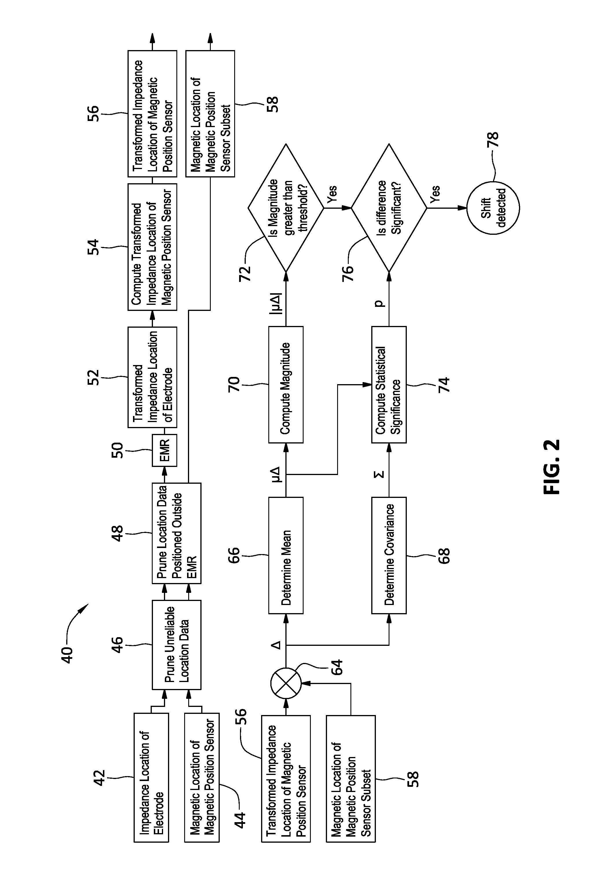
This patent describes a method for detecting and correcting an impedance shift in a coordinate system. The method uses electromagnetic registration to transform and compare the impedance location of an electrode in an impedance based coordinate system with the magnetic location of a magnetic position sensor in a magnetic based coordinate system. A difference between the two is determined, indicating an impedance shift. The magnitude of the difference is computed, and a statistical significance is determined to confirm the presence of a significant shift. The patent also covers correcting the shifted impedance location of the electrode in the magnetic based coordinate system using a second electromagnetic registration. Overall, the patent provides a method for accurately detecting and correcting impedance shifts in a coordinate system.

Problems solved by technology

For example, an impedance-based localization system offers the ability to track numerous localization elements simultaneously, but is susceptible to inhomogeneities in the electrical field and shift and / or drift resulting from varying impedance regions and other external factors.
Such systems, however, require special sensors to be used as localization elements and, as such, are relatively limited in the number of localization elements that can be simultaneously tracked.

Method used


Image

  • Impedance shift and drift detection and correction
  • Impedance shift and drift detection and correction
  • Impedance shift and drift detection and correction

Examples


Embodiment Construction

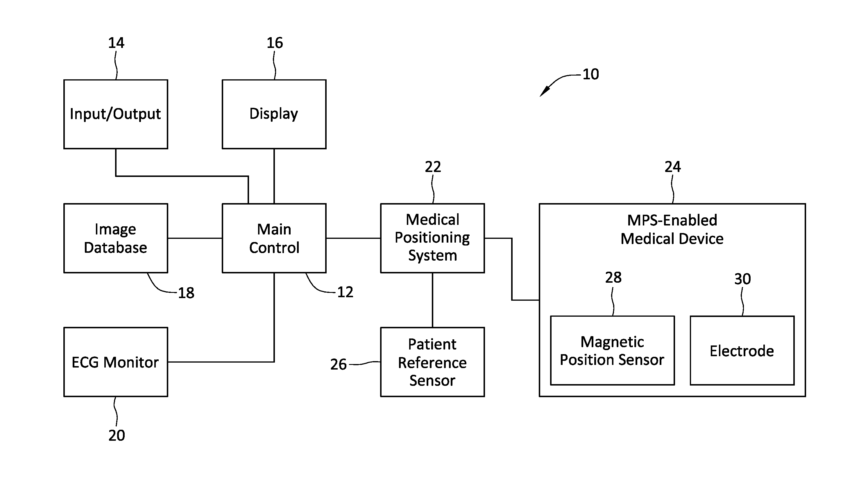
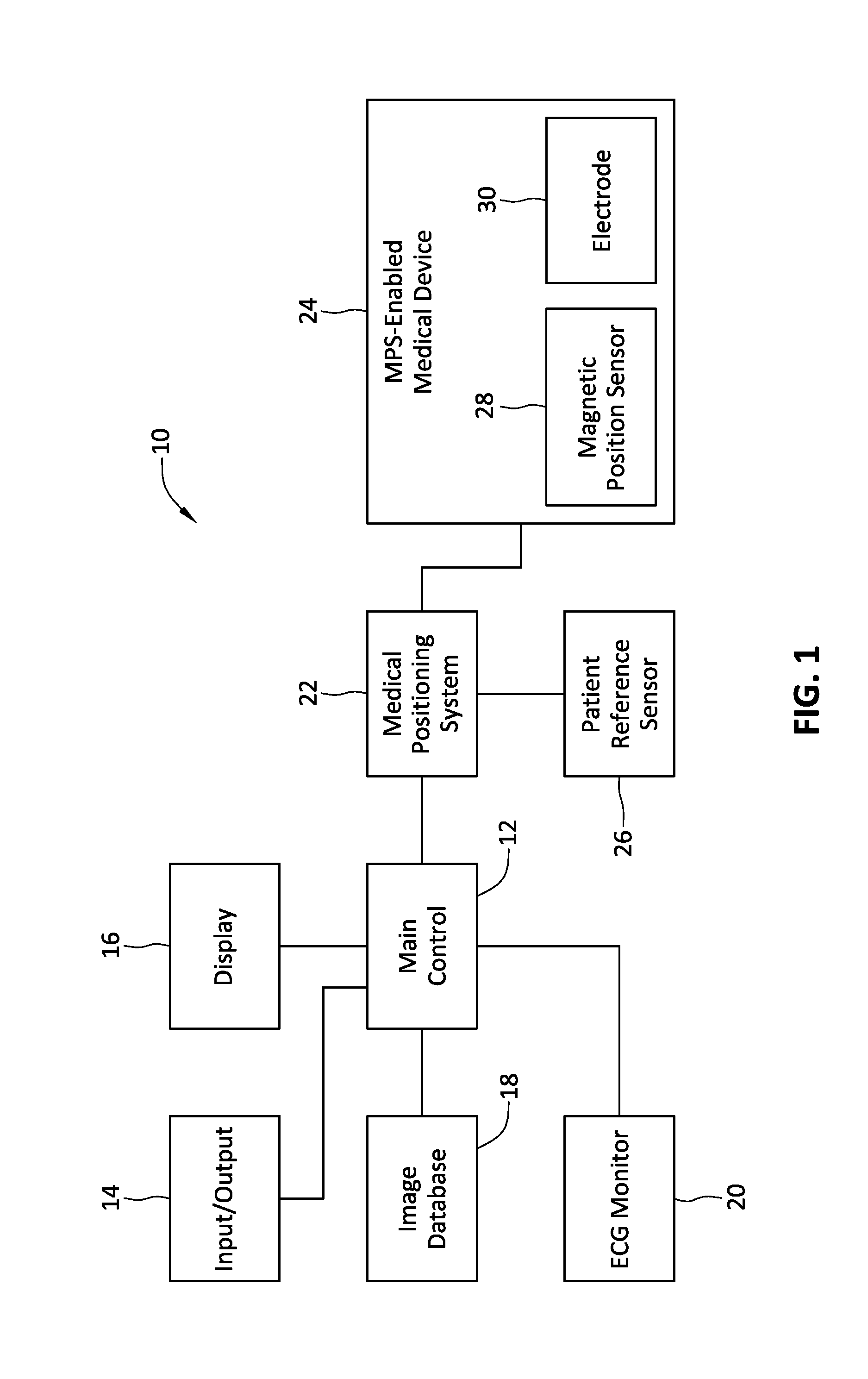
[0014]Referring now to the drawings wherein like reference numerals are used to identify identical or similar components in the various views, FIG. 1 is a diagrammatic view of a system 10 in which a medical device, such as a guidewire, catheter, introducer (e.g., sheath) incorporating an magnetic position sensor 28 and an electrode 30 may be used.

[0015]Before proceeding to a detailed description of the embodiments of the present disclosure, a description of an exemplary environment in which such devices and sensors may be used will first be set forth. With continued reference to FIG. 1, system 10, as depicted, includes a main electronic control unit 12 (e.g., a processor) having various input / output mechanisms 14, a display 16, an optional image database 18, an electrocardiogram (ECG) monitor 20, a localization system, such as a medical positioning system 22, a medical positioning system-enabled elongate medical device 24, a patient reference sensor 26, a magnetic position sensor 28...


PUM


Abstract

An impedance location of an electrode in an impedance based coordinate system and a magnetic location of a magnetic position sensor in a magnetic based coordinate system can be received. A transformed impedance location of the magnetic position sensor can be computed. A difference between the transformed impedance location of the magnetic position sensor and the magnetic location of the magnetic position sensor can be determined. A magnitude of the difference between the impedance location of the magnetic position sensor and the magnetic location of the magnetic position sensor can be computed. A statistical significance of the difference between the transformed impedance location of the magnetic position sensor and the magnetic location of the magnetic position sensor can be computed. A determination can be made that an impedance shift exists if the magnitude of the difference exceeds a threshold and a statistical significance of the difference exceeds a threshold.

Description

CROSS-REFERENCE TO RELATED APPLICATION[0001]This application is related to the application with docket no. CD-1054W001 (065513-001426) entitled “IMPEDANCE SHIFT AND DRIFT DETECTION AND CORRECTION”, filed 20 Jun. 2016. This application claims priority to U.S. provisional patent application No. 62 / 182,208 entitled “IMPEDANCE SHIFT AND DRIFT DETECTION AND CORRECTION”, filed 19 Jun. 2015, which is hereby incorporated by reference as though fully set forth herein.BACKGROUND[0002]a. Field[0003]The present disclosure relates generally to impedance shift and drift detection and correction.[0004]b. Background[0005]The three-dimensional coordinates of a catheter or other medical device moving within a patient's body are often tracked using a localization system (sometimes also referred to as a “mapping system,”“navigation system,' or positional feedback system”). These devices typically use magnetic, electrical, ultrasound, and other radiation sources to determine the coordinates of these dev...

Claims


Application Information

Patent Timeline
Patent Type & Authority Applications(United States)
IPC IPC(8): A61B34/20A61M25/01A61B5/06
CPCA61B34/20A61B5/062A61B5/068A61B2034/2065A61B5/066A61B2034/2053A61M2025/0166A61M25/0127A61B1/00158A61B5/063A61B5/7203A61B5/7221A61B5/7264
Inventor MALININ, YURIYHILL, ANTHONY D.THOMPSON, CABLE P.
Owner ST JUDE MEDICAL CARDILOGY DIV INC
Learn More