Machine tool

Inactive Publication Date: 2016-12-22
MURATA MASCH LTD +1
View PDF10 Cites 8 Cited by
  • Summary
  • Abstract
  • Description
  • Claims
  • Application Information

AI Technical Summary

Benefits of technology

[0010]According to a preferred embodiment of the present invention, the first surface of the cutting tool is in contact with the first reference surface of the holder, and the second surface of the cutting tool is in contact with the second reference surface of the holder. Thus, it is possible to easily position the cutting tool with respect to the holder and to accurately set the orientation of the linear cutting blade along the plane parallel or substantially parallel with the rotation axis. Further, the cutting tool is able to be easily mounted on the holder. Since there is no need to form a keyway, protrusion, or the like in the cutting tool or holder but rather a simple configuration is used, the production cost of the holder, cutting tool, and the like is significantly reduced.
[0011]In the case of the configuration in which at least one of the first reference surface and the second reference surface is disposed in a position that receives a reaction force when cutting the workpiece, at least one of the first reference surface and second reference surface supports the reaction force of the cutting tool that acts when cutting the workpiece. Thus, the misalignment of the cutting tool is able to be prevented. In the case of

Problems solved by technology

In this configuration, the reference surfaces of the holder are inclined with respect to the linear cutting blade and therefore the linear cutting blade is difficult to position accurately.
However, fixing the cut

Method used


Image

  • Machine tool
  • Machine tool
  • Machine tool

Examples


first preferred embodiment

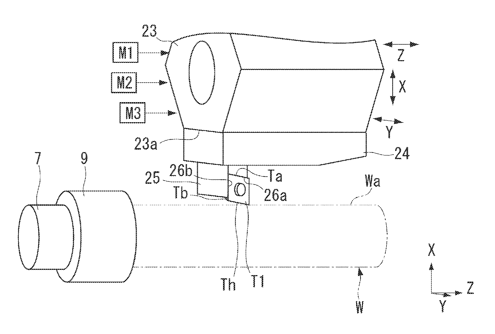
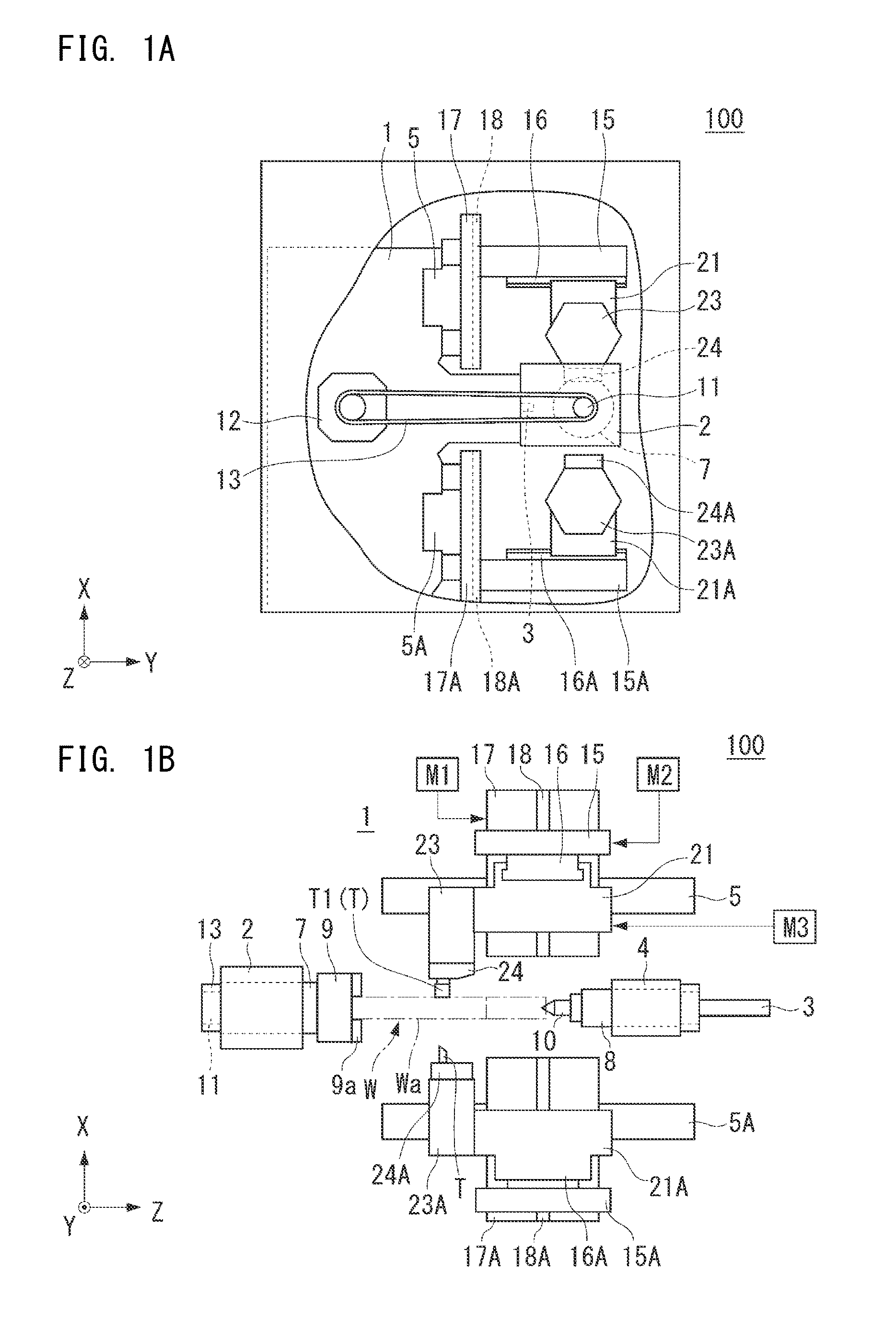
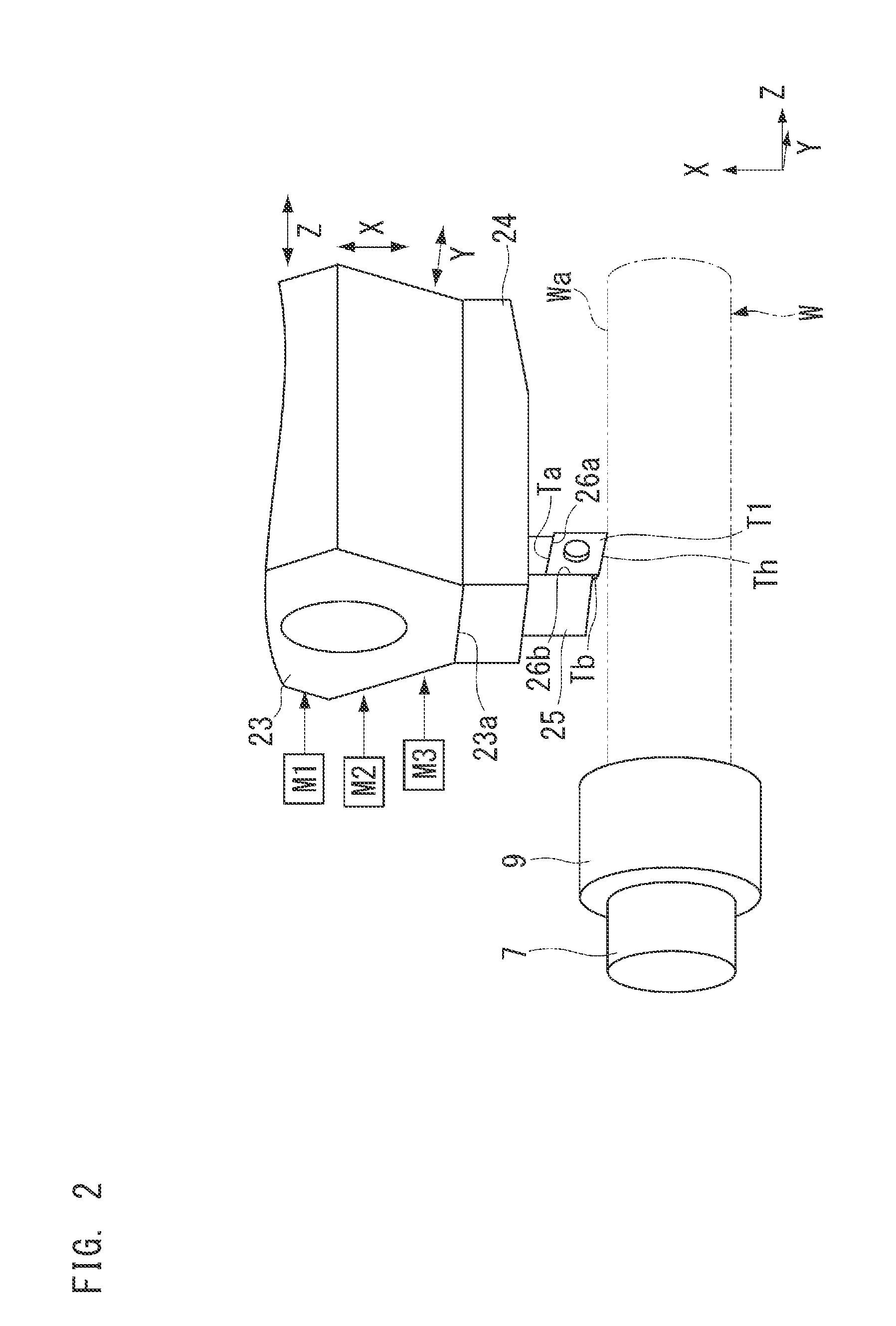
[0021]A machine tool 100 of a first preferred embodiment of the present invention will be described with reference to the drawings. FIGS. 1A and 1B are diagrams showing an example of a major portion of the machine tool 100 of the first preferred embodiment, in which FIG. 1A is a side view; and FIG. 1B is a front view. The machine tool 100 shown in FIGS. 1A and 1B is a lathe. In FIGS. 1A and 1B, the front side of the machine tool 100 is located on the positive Y side, and the back side thereof is located on the negative Y side. The lateral sides of the machine tool 100 are located on the positive and negative Z sides, and the Z-direction represents the horizontal direction of the machine tool 100.

[0022]As shown in FIGS. 1A and 1B, the machine tool 100 includes a base 1. The base 1 includes a headstock 2 and a tailstock 4. The headstock 2 rotatably supports a main spindle 7 with a bearing or the like (not shown) therebetween. While the headstock 2 is fixed to the base 1, it may be mov...

second preferred embodiment

[0061]A machine tool 200 of a second preferred embodiment of the present invention will be described. FIGS. 7A and 7B include diagrams showing an example of a major portion of the machine tool 200 of the second preferred embodiment, in which FIG. 7A is a perspective view showing an example of a cutting tool T1 and a holder; and FIG. 7B is a perspective view showing an example of a holder. Note that elements not shown in FIGS. 7A and 7B are similar to those of the machine tool 100 shown in FIGS. 1A and 1B.

[0062]As shown in FIG. 7A, a holder 125 is fixed to a tool head 124. As with the tool head 24 of the first preferred embodiment, the tool head 124 is mounted on a tool post, such as a first turret 23, using a bolt or the like. The tool head 124 includes a recess on the negative Z-side thereof and includes a clamp contact surface 124a and a holder contact surface 124b which are opposed to each other in the Y-direction. The interval between the clamp contact surface 124a and holder co...


PUM

PropertyMeasurementUnit
Forceaaaaaaaaaa
Diameteraaaaaaaaaa

Abstract

A machine tool includes a moving device that moves a cutting tool with a linear cutting blade in a Y-direction, or in a combined direction of the Y-direction and a Z-direction, with an axis of a main spindle holding a workpiece, an X-direction determines an amount of cutting of the workpiece, and a holder that holds the cutting tool such that the orientation of the linear cutting blade is inclined with respect to the Z-direction when seen from the X-direction. The holder includes a first reference surface contacting with a first surface parallel with a linear cutting blade, of the side surfaces of the cutting tool and is parallel with the YZ-plane or a plane tangent to the peripheral surface of the workpiece and a second reference surface that is in contact with a second surface intersecting the first surface. The workpiece is cut while moving the linear cutting blade in the Y-direction or the combined direction.

Description

BACKGROUND OF THE INVENTION[0001]1. Field of the Invention[0002]The present invention relates to a machine tool that cuts a workpiece.[0003]2. Description of the Related Art[0004]A lathe, which is a machine tool, holds a workpiece to be machined, on the rotation axis (spindle) and performs cutting or the like on the workpiece using a machining tool, such as a cutting tool, while rotating the workpiece (see Japanese Patent No. 2701706). As a machining method using a lathe, for example, there is known a machining method of cutting a workpiece while feeding a cutting tool in the tangential direction of a workpiece (a direction crossing the rotation axis). In this machining method, a triangular or rectangular cutting tool provided with a linear cutting blade is used with it mounted on a holder. When the workpiece is cut as described above with the linear cutting blade inclined with respect to a plane parallel or substantially parallel with the rotation axis of the workpiece (a plane inc...

Claims


Application Information

Patent Timeline
IPC IPC(8): B23B3/06B23B29/04B23B27/16
CPCB23B3/06B23B29/04B23B27/16B23B1/00
Inventor ISHIHARA, TADASHITANAKA, KUNISHIGE
Owner MURATA MASCH LTD
Why Eureka
Try Eureka