Eureka AIR delivers breakthrough ideas for toughest innovation challenges, trusted by R&D personnel around the world.

Aircraft landing gear assembly

a technology for landing gear and assembly, which is applied in the direction of spring/damper design characteristics, undercarriage, wheel arrangement, etc., can solve the problem of adversely affecting the ability of the shock absorber to close quickly

Active Publication Date: 2016-12-29
MESSIER DOWTY
View PDF0 Cites 7 Cited by
  • Summary
  • Abstract
  • Description
  • Claims
  • Application Information

AI Technical Summary

Benefits of technology

The landing gear assembly described in this patent is a unique design that combines a conventional shock absorber with a non-pneumatic, mechanical spring. This dual stage shock absorber is designed to allow for the measurement of the initial compression of the structure, which can facilitate a comfortable landing for the aircraft. The design is simple and lightweight, and can be easily integrated with existing shock absorber systems. The technical effects include improved load absorption and reduced size and weight of the sensor.

Problems solved by technology

While the breakout force does not adversely affect normal operation of the shock absorber, it can adversely affect the shock absorber's ability to close rapidly during light landings, where the aircraft landing force acting on the shock absorber is below average.

Method used


Image

  • Aircraft landing gear assembly
  • Aircraft landing gear assembly
  • Aircraft landing gear assembly

Examples


Embodiment Construction

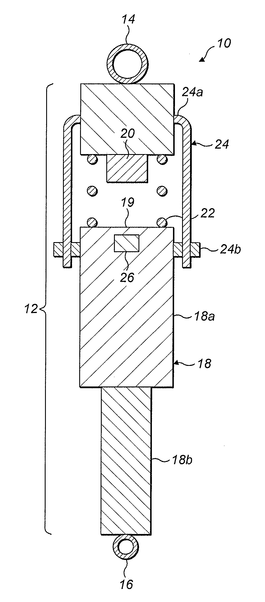
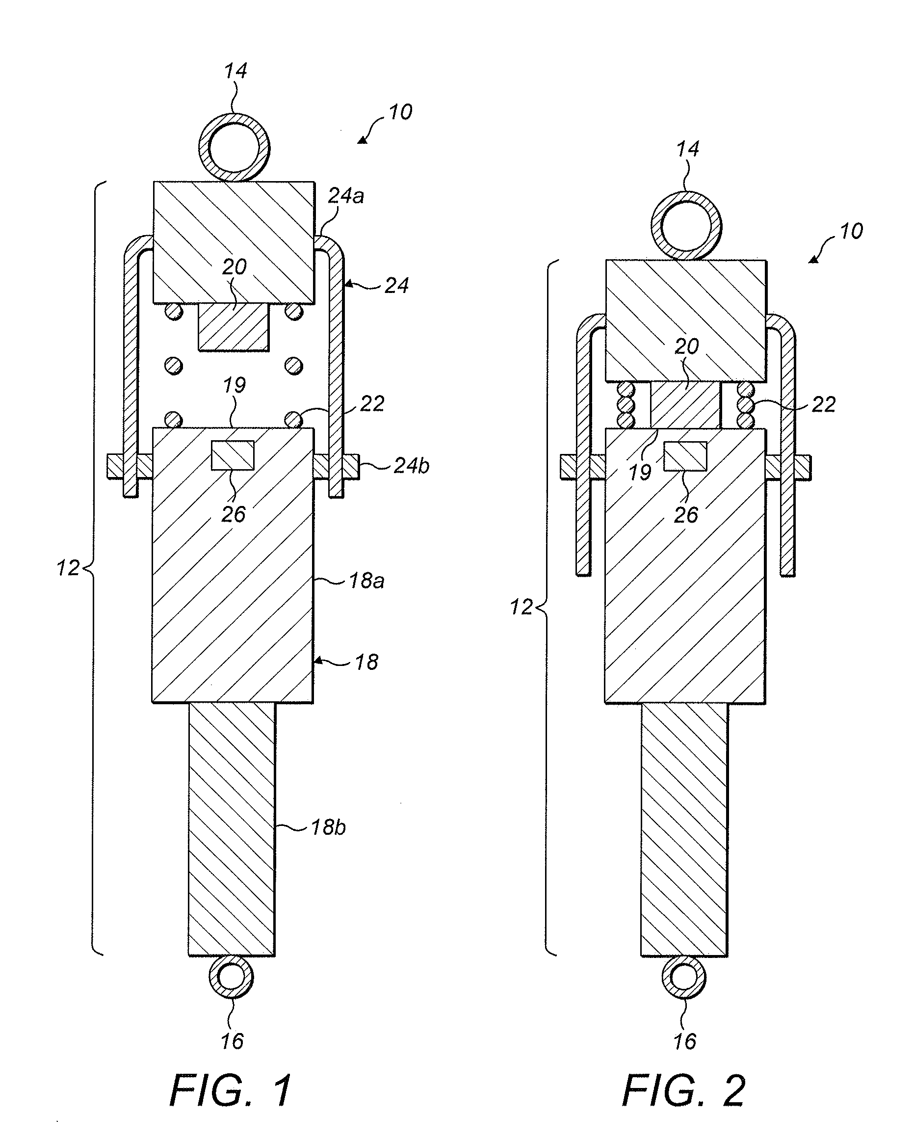
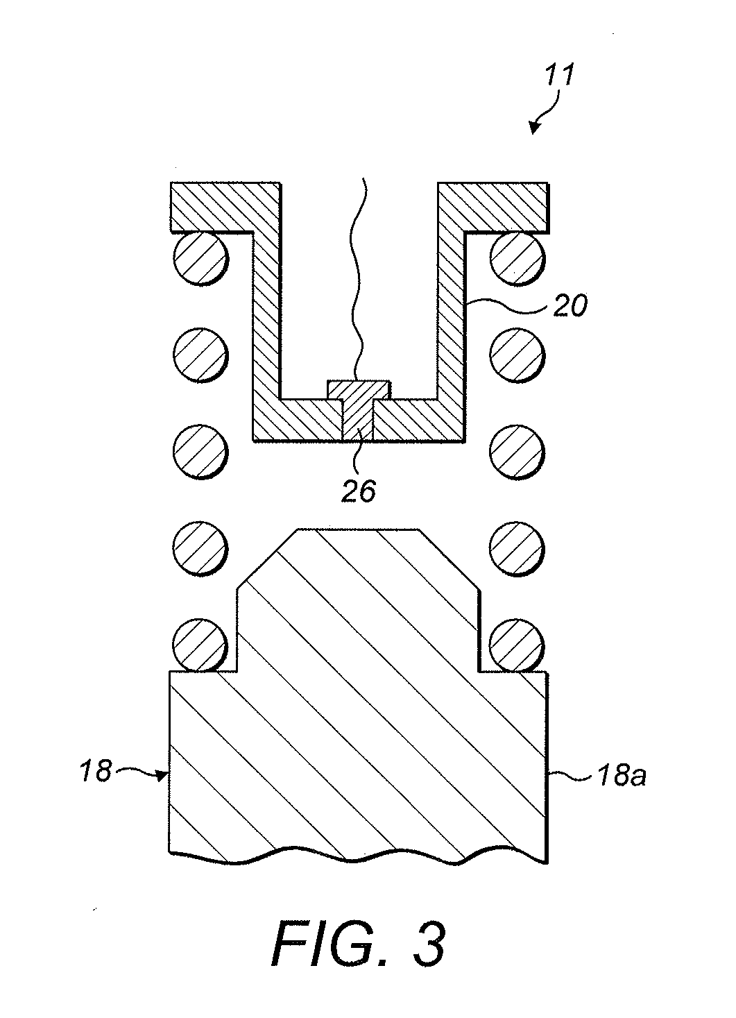
[0043]FIG. 1 shows a diagram of shock absorber assembly 10 according to an embodiment of the present invention. The shock absorber assembly 10 is arranged to form part of an aircraft assembly such as a landing gear assembly (not shown). For example, the shock absorber assembly 10 can define the main landing gear strut in a main landing gear assembly.

[0044]The shock absorber assembly 10 includes a mounting coupling 14 by which the shock absorber assembly 10 is arranged to be movably coupled to an aircraft not shown so as to be moveable between a deployed position for take-off and landing, and a stowing condition for flight. However, in other embodiments the shock absorber assembly can be arranged to form part of a fixed landing gear.

[0045]A structural linkage 12 exists between the mounting coupling 14 and the wheel assembly coupling 16. The structural linkage 12 defines a mechanical load path between the mounting coupling 14 and the wheel assembly coupling 16 capable of reacting airc...


PUM


Abstract

An aircraft landing gear assembly includes a mechanical structural linkage having a shock absorber and a linkage abutment which are biased apart by a mechanical spring. The force required to deform the spring sufficiently to place the linkage abutment at a predefined distance with respect to the shock absorber abutment is less than the breakout force of the shock absorber.

Description

[0001]This Application claims priority to and the benefit of European Application 15170283.4, filed on Jun. 2, 2015, which is incorporated herein by reference in its entirety.BACKGROUND TO THE INVENTION[0002]Aircraft on-board control systems typically require a ‘weight on wheels’ or ‘weight off wheels’ signal (each of which will be referred to as a ‘WoW’ signal) to be detected before allowing an operator to perform certain landing-specific functions, such as deploying lift dumping devices and applying landing gear brakes.[0003]It is known to use mechanical closure of the main shock absorbing strut to provide a WoW signal; for example, a sensor such as a proximity sensor can be switched on when a main shock absorbing strut attains a predetermined state of compression. Such sensors will be referred to herein as compression-based WoW sensors.[0004]The design of aircraft landing gear shock absorbers is often a compromise between shock absorber simplicity and the need to balance the weig...

Claims


Application Information

Patent Timeline
Patent Type & Authority Applications(United States)
IPC IPC(8): B64C25/62F16F13/00B64C25/60B64C25/34B64C25/10
CPCB64C25/62B64C25/34B64C25/10F16F2226/04F16F13/007F16F2230/0023B64C25/60F16F9/3292F16F9/54F16F9/0218
Inventor SCHMIDT, ROBERT KYLE
Owner MESSIER DOWTY
Why Eureka
Eureka Blog
Learn More