Drilling rig arrangement

a drilling rig and arrangement technology, applied in the direction of drilling pipes, waterborne vessels, fluid removal, etc., can solve the problems of increasing the cost of drilling rigs, increasing the cost of drilling rigs. , to achieve the effect of increasing the cost of drilling rigs, increasing safety, and facilitating fabrication, installation and maintenan

Active Publication Date: 2016-12-29
CASTOR DRILLING SOLUTION
View PDF0 Cites 7 Cited by
  • Summary
  • Abstract
  • Description
  • Claims
  • Application Information

AI Technical Summary

Benefits of technology

[0014]The present invention relates to a development of a cost and energy efficient concept for drilling and intervention tower with accompanying elevator/draw-work system that is flexible with a focus on increased security and is easier in terms of fabrication, installation and maintenance. Central to this technology development is more suitability for operations in arctic waters and it is also more adaptable to different types and sizes of the vessel or the platform. The concept includes a cylindrical tower-/mast construction with wire sheaves at the top to support a balanced lifting of the travelling assembly. The tower is telescopic ie it could be lowered and raised and has a flanged fastening point towards the drilling floor structure. The tower/mast comprising at least two segments that allows the upper segment of the tower to be lifted and lowered in the lower segment by means of typical internal toothed rod drives to reduce the building and sailing height. At the top of the drilling rig, there are mounted lifting sheaves where the lifting wires are guided above.
[0015]Lifting and compensating for the top drive or drilling tool and landing of pipe segments to the seabed is carried out by means of a combined/integrated winch and a heave compensator located...

Problems solved by technology

This could result in challenges related to security, the lifetime of the cable and noises due to the high speed of the cable and in the winch system.
The passive compensation systems in the top of drilling rig is heavy and not easily accessible for maintenance.
Considerable weight in the top of the derrick is detrimental to the properties of the vessel.
In case of active draw-work-configuration the rig have no back-up in case of possible loss of...

Method used


Image

  • Drilling rig arrangement
  • Drilling rig arrangement
  • Drilling rig arrangement

Examples


Embodiment Construction

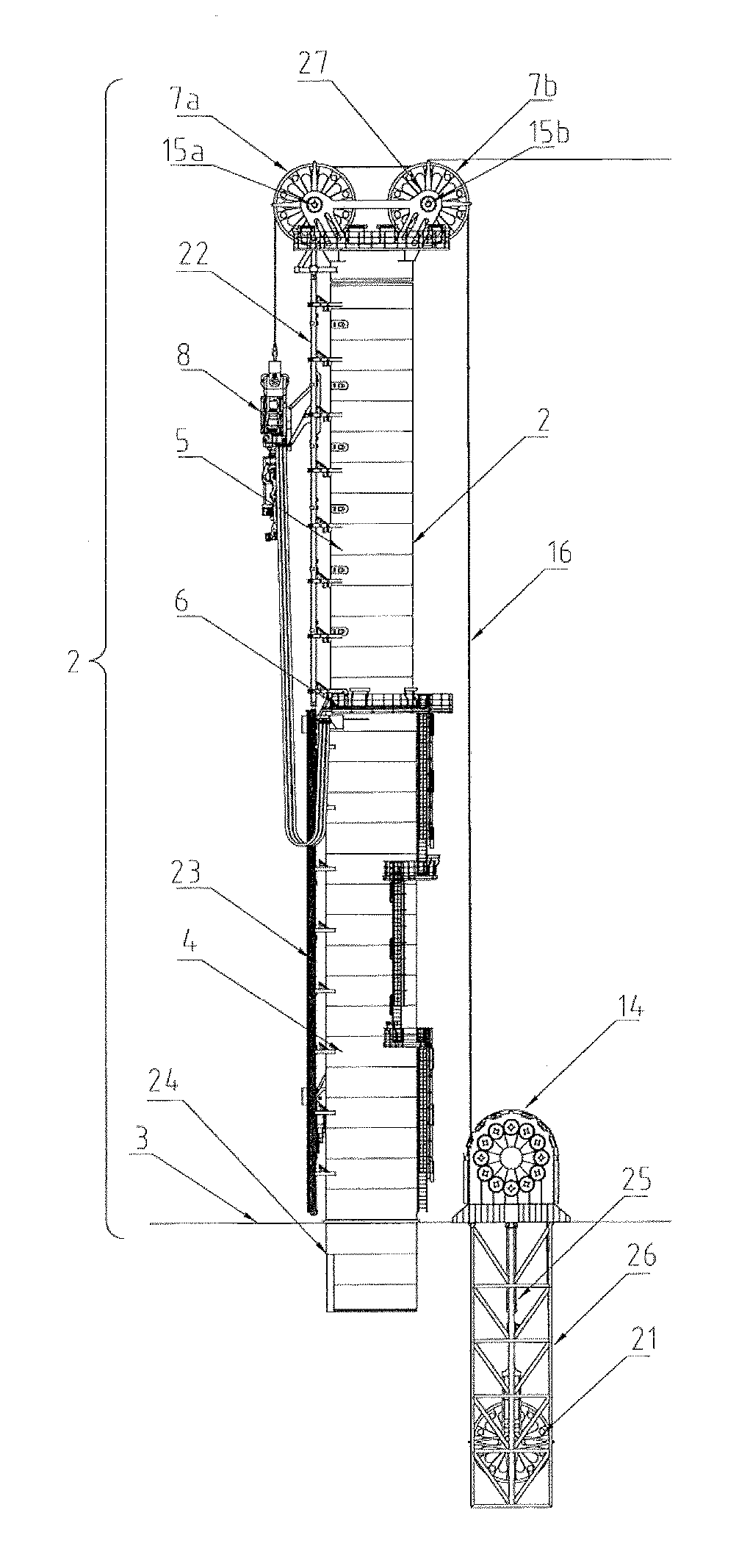
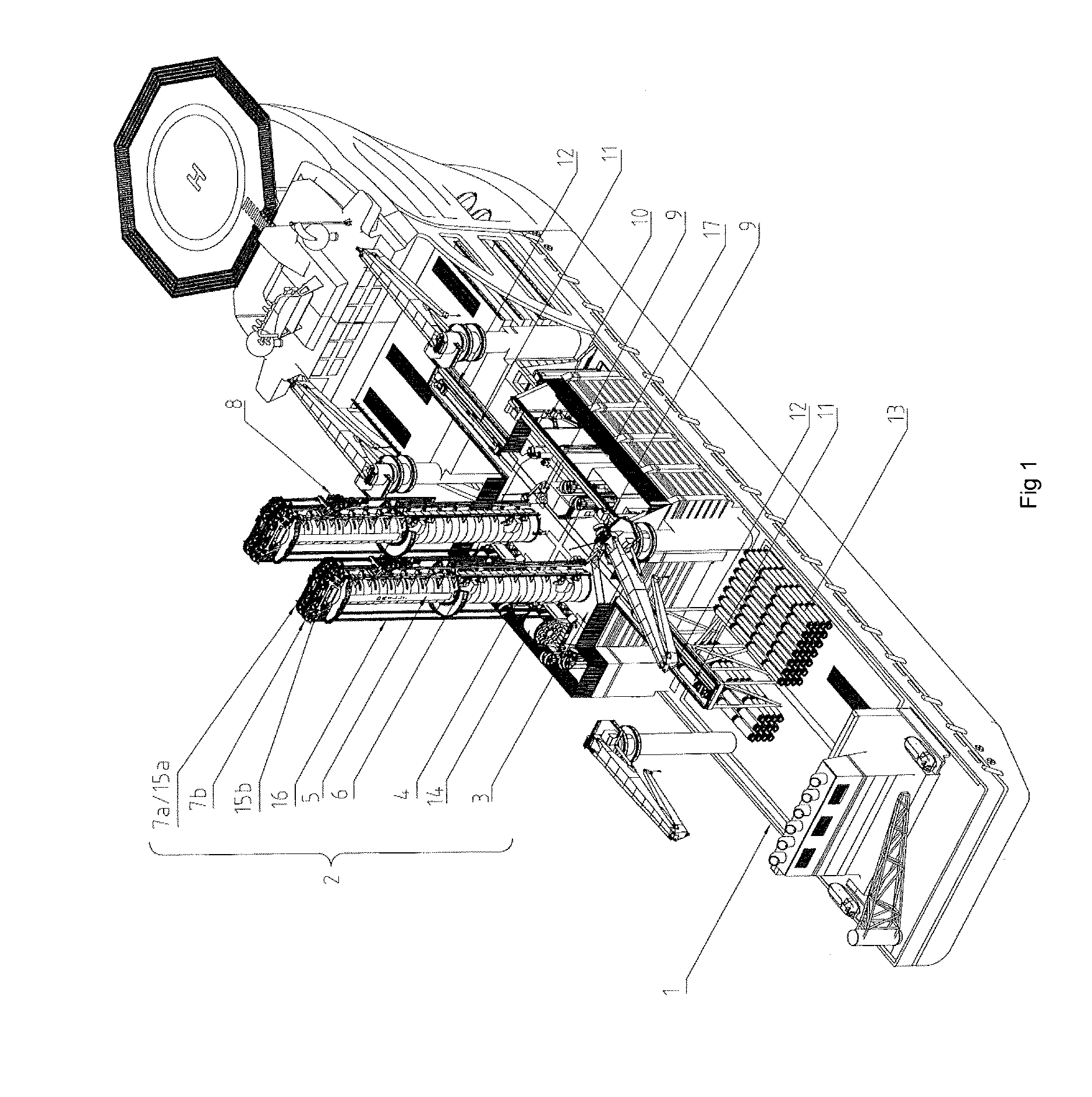
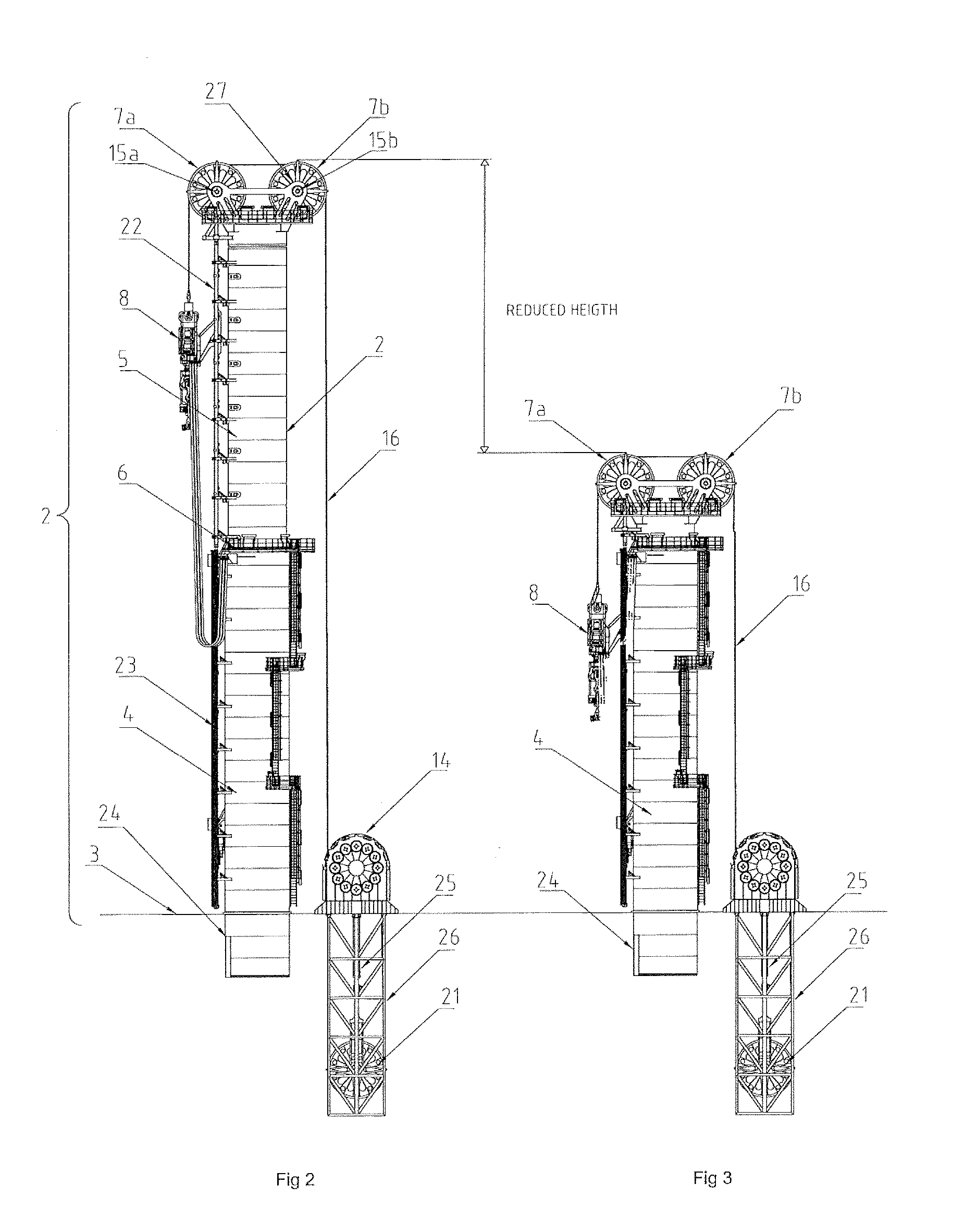
[0049]FIG. 1 shows a drilling rig arrangement mounted on a drilling vessel 1. The Figure shows two equal retractable drilling towers 2 connected to a rig floor 3 on the vessel 1. The drilling rig towers 2 are arranged, next to one another on the vessel 1. The drilling rig towers 2 are shown in an elevated position in the figure and comprising a first, lower segment 4 and a second, upper segment 5. The second segment 5 is retractable within the first segment 4. A possible embodiment of the invention is a drilling rig tower 2 with more than two segments comprising a base segment, one or more middle segments and an upper segments. The middle and the upper segments are retractable. Well center 9 are arranged beside each of the towers 2. The towers 2 are mounted to the rig floor outside of the well center 9. A top drive 8 or main block are arranged in a vertical line above the well center 9, suspended from a at least one wire 16, and is adapted to be in operational connection with the we...


PUM


Abstract

The invention provides a system for operating a drilling rig on a drilling vessel, the system comprising a drilling tower (2) having at least two segments (4, 5), a first segment (4) is fixedly connected to the drilling vessel (1), a second segment (5) is connected to the first segment (4), said second segment (5) is adapted to move longitudinally relative the first segment (4) by raising and lowering means. A tool (8) is suspended from at least one wire (16), said at least one wire (16) is extending over at least one sheave (7a, 7b) on top of the second segment (5), said at least one wire (16) is coupled to with a passive compensator arrangement (20) and a winch (14), said passive compensator (20) is connected to the winch (14).

Description

FIELD OF THE INVENTION[0001]The present invention relates to an arrangement for a drilling rig that serves as supporting tower structure for lifting and supporting drilling machines and other tools. More particularly the invention relates to a retractable drilling rig with a passive heave compensation system and winch system arranged in connection with the drilling rig.BACKGROUND OF THE INVENTION AND PRIOR ART[0002]Drilling ships and semi-submersible platforms are equipped with drilling rigs to support the necessary lifting of equipment under various offshore operations. Usually, these derricks are equipped with passive and active compensator systems to compensate for relative movements between the vessel and the seabed due to vessel wave impact.[0003]The wave compensation systems are designed for handling of maximum loads at the seabed or down hole. This is often overcome by installing a passive compensator in the top of the drilling rig. This passive compensator compensates the we...

Claims


Application Information

Patent Timeline
IPC IPC(8): E21B15/02E21B19/09
CPCE21B19/09E21B15/02B63B35/4413E21B19/02B63B2003/147
Inventor TARALDRUD, PAAL ANDERSREITEN, OYVIND VAAGLAND
Owner CASTOR DRILLING SOLUTION
Why Eureka
Try Eureka