Combustion apparatus

Active Publication Date: 2016-12-29
RINNAI CORP
View PDF13 Cites 13 Cited by
  • Summary
  • Abstract
  • Description
  • Claims
  • Application Information

AI Technical Summary

Benefits of technology

[0011]According to this arrangement, an overall air-fuel ratio of the lean air-fuel mixture to be ejected from the burner ports of the second gas burners becomes air-richer than the air-fuel ratio of the lean air-fuel ratio of the lean air-fuel mixture to be ejected from the burner ports of the first gas burners. As a consequence, the difference becomes larger between such frequencies of the combustion vibrations of the lean air-fuel mixture as are generated in the second gas burners and such frequencies of the combustion vibrations of the lean air-fuel mixture as are generated in the first gas burners, whereby the combustion noises can be effectively reduced. Further, the rich air-fuel mixture to be ejected from the flame retention burner ports of the second gas burners changes in the air-fuel ratio to the gas-rich side due to the limitation of the primary air by the second flame retention ventilation holes. Therefore, even if the air-fuel ratio of the lean air-fuel mixture to be ejected from the burner ports of the second gas burners may be changed to the air-rich side, the amount of such primary air in the lean air-fuel mixture as is consumed in the combustion of the rich air-fuel mixture to be ejected from the flame retention burner port of the second gas burner increases. In this manner, lifting of the lean flame at the time of high intensity combustion (flames to be formed by the combustion of the lean air-fuel mixture) by the second gas burner can be suppressed. Still furthermore, the air-fuel ratio of the rich air-fuel mixture to be ejected from the flame retention burner port of the first gas burner is different from the air-fuel ratio of the rich air-fuel mixture to be ejected from the flame

Problems solved by technology

However, if the air-fuel ratio of the air-fuel mixture is varied to the air-rich side by enlarging the area of

Method used


Image

  • Combustion apparatus
  • Combustion apparatus
  • Combustion apparatus

Examples


Embodiment Construction

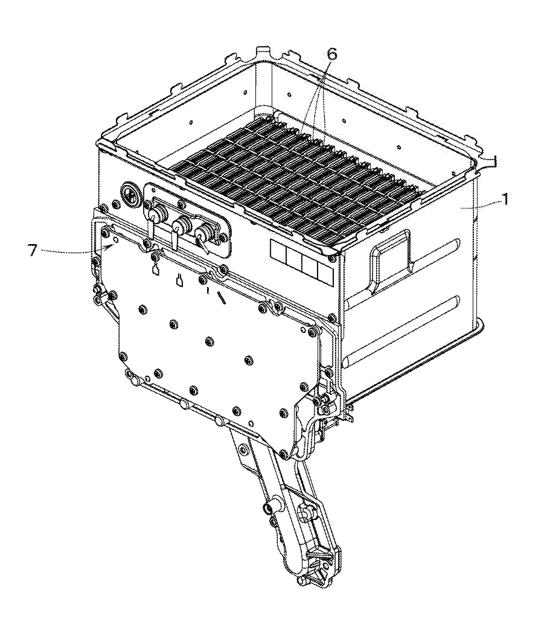
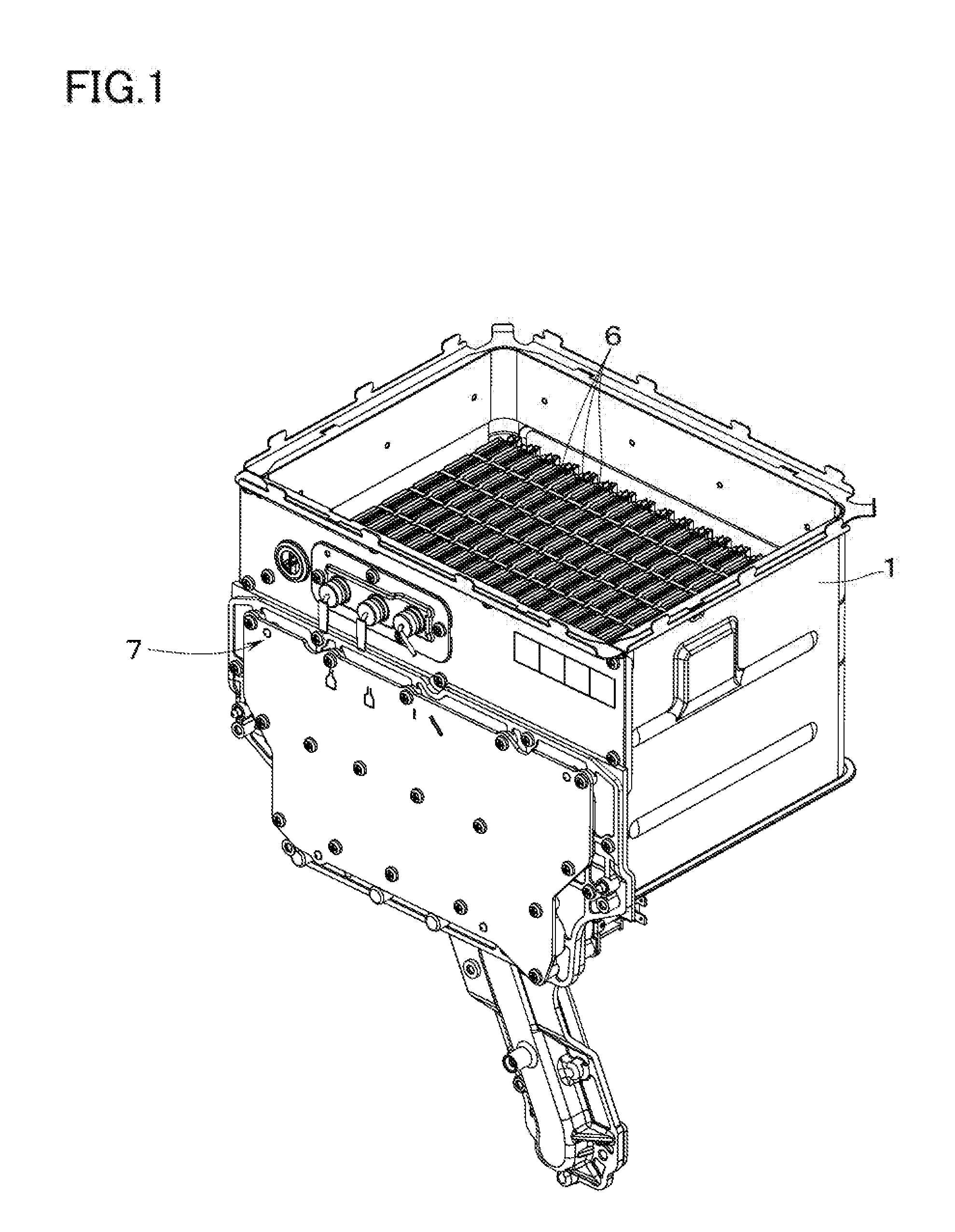
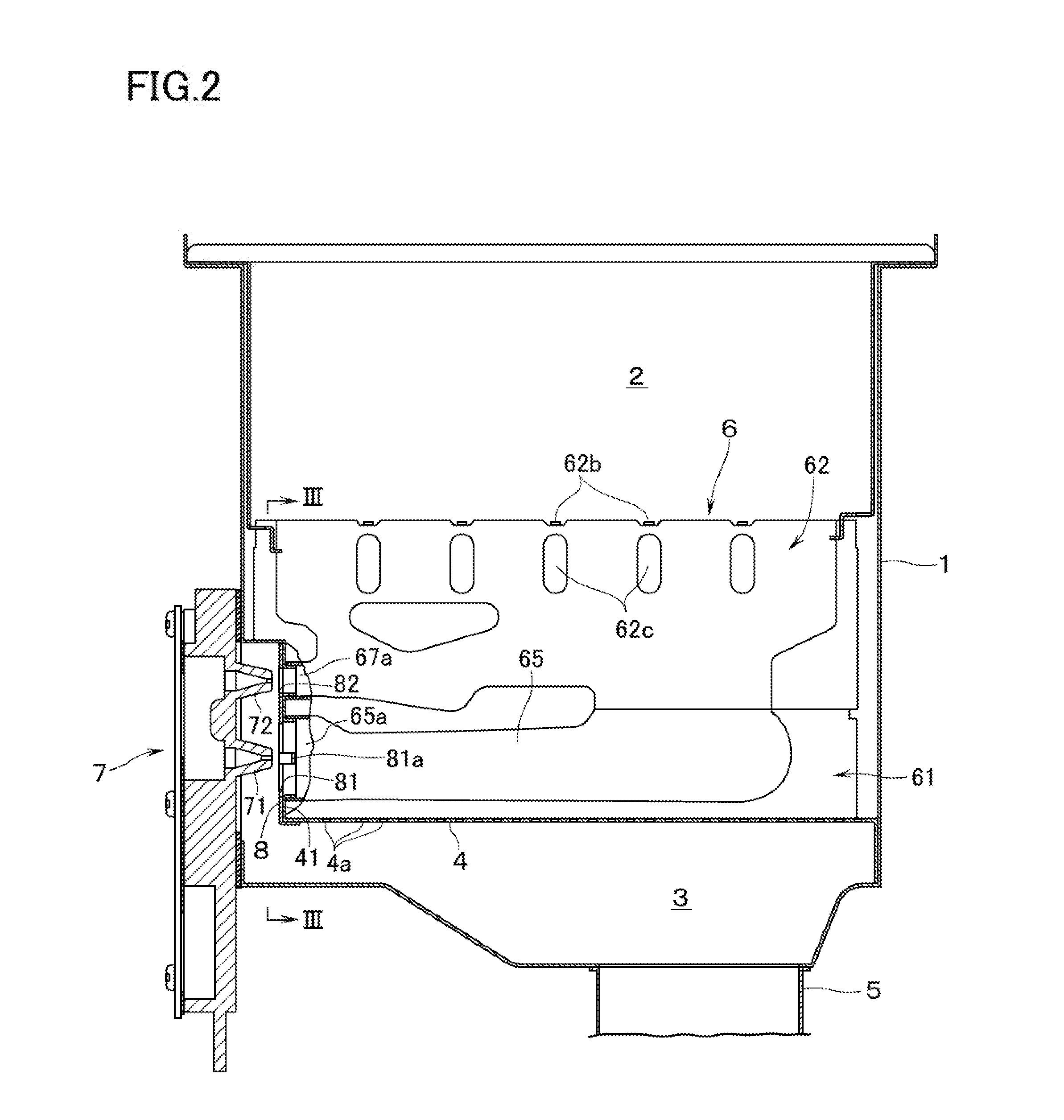
[0019]With reference to FIGS. 1 through 3, the combustion apparatus according to an embodiment of this invention is provided with a combustion box 1. The upper surface of the combustion box 1 is left open. On top of the combustion box 1 there is disposed, as an object to be heated, a heat exchanger (not illustrated) for supplying hot water. Inside the combustion box 1 there is disposed a partition plate 4 which partitions the space inside the combustion box 1 into a combustion chamber 2 and an air supply chamber 3 which lies on a lower side of the combustion chamber 2. To the bottom surface of the air supply chamber 3 there is connected a combustion fan (not illustrated) through a duct 5 so that air can be supplied from the combustion fan to the air supply chamber 3. The partition plate 4 has formed therein a multiplicity of distribution holes 4a so that the air supplied to the air supply chamber 3 can be supplied, as secondary air, to the combustion chamber 2 through these distribu...


PUM


Abstract

A combustion apparatus has a plurality of longitudinally elongated gas burners, each having a burner port on an upper end thereof. A damper is disposed to cover gas inlet ports on an upstream end of an air-fuel mixing tube portion of each of the gas burners. The damper has formed therein ventilation holes for limiting primary air. The ventilation holes overlap, and are smaller than, the gas inlet ports. The damper has #1 ventilation holes having obstacles against which the fuel gas to be ejected from the gas nozzles strike, and #2 ventilation holes without obstacles. Poor combustion such as flame lifting is restricted and combustion noises are reduced.

Description

BACKGROUND OF THE INVENTION[0001]1. Technical Field[0002]The present invention relates to a combustion apparatus comprising a plurality of longitudinally (in the back-and-forth direction) elongated gas burners, each of the gas burners having an air-fuel mixing tube portion, and a burner port on an upper end of the gas burner for ejecting air-fuel mixture from the air-fuel mixing tube portion.[0003]2. Background Art[0004]This kind of combustion apparatus is provided with a plurality of gas nozzles each lying opposite to a gas inlet port which is on an upstream end of the air-fuel mixing tube portion of each of gas burners, and a damper to cover the plurality of gas inlet ports of the plurality of gas burners. The damper has formed therein ventilation holes which overlap the gas inlet ports of the plurality of gas burners. Conventionally, there is known an arrangement in which each of the ventilation holes is provided with obstacles to which fuel gas to be ejected from the gas nozzles...

Claims


Application Information

Patent Timeline
IPC IPC(8): F23D14/02F23D14/64
CPCF23D14/64F23D14/02F23C5/08F23C7/02F23C2700/04F23D14/045F23D14/105F23D14/26F23D14/70F23D14/08F23D14/74F23D2203/007F23D2209/20
Inventor SUGIOKA, SHINGOONO, TAKAHIROOKAMOTO, HIDEO
Owner RINNAI CORP
Why Eureka
Try Eureka