Actuator

a technology of actuators and actuators, applied in the field of actuators, can solve the problems of disadvantageous increase in the size of the rotational angle sensing device and limited actuator costs, and achieve the effect of limited failure of detectors caused by gear oil scattering

Inactive Publication Date: 2017-01-05
DENSO WAVE INC
View PDF2 Cites 4 Cited by
  • Summary
  • Abstract
  • Description
  • Claims
  • Application Information

AI Technical Summary

Benefits of technology

[0010](5) The actuator of the above aspect may further include a control board, which has a control unit that controls the electric motor, wherein: each of the two angle sensing devices may include: a magnet that is installed to a corresponding one of the two sensing-subject shaft members; and a detector that is installed to the control board and detects a magnetic flux generated from the magnet; a portion of a housing, which rotatably supports the at least two intermediate shaft members and the output shaft member, may be interposed between the magnet and the detector of each of the two angle sensing devices; and the portion of the housing may be made of a non-magnetic material. In the actuator of this aspect, a portion of the housing serves as a shield that limits scattering of the gear oil, which lubricates the large diameter gears and the small diameter gears fixed to the intermediate shaft members and the output gear fixed to the output shaft member, onto the detectors of the two angle sensing devices, so that failure of the detectors caused by the scattering of the gear oil can be limited.
[0011](6) According to another aspect the present disclosure, there is provided another actuator to be used at the joint of the robot. The actuator includes an electric motor; an input shaft member that is rotated about an axis of the input shaft member by rotation of the e

Problems solved by technology

However, in the rotational angle sensing device recited in the Patent Literature 1, when a diameter of the shaft, the rotational angle of which is s

Method used


Image

  • Actuator
  • Actuator
  • Actuator

Examples


Embodiment Construction

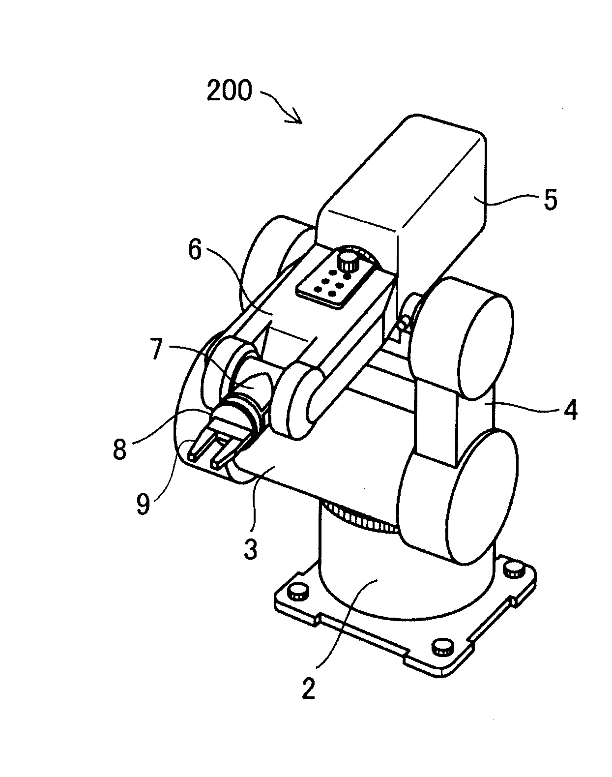
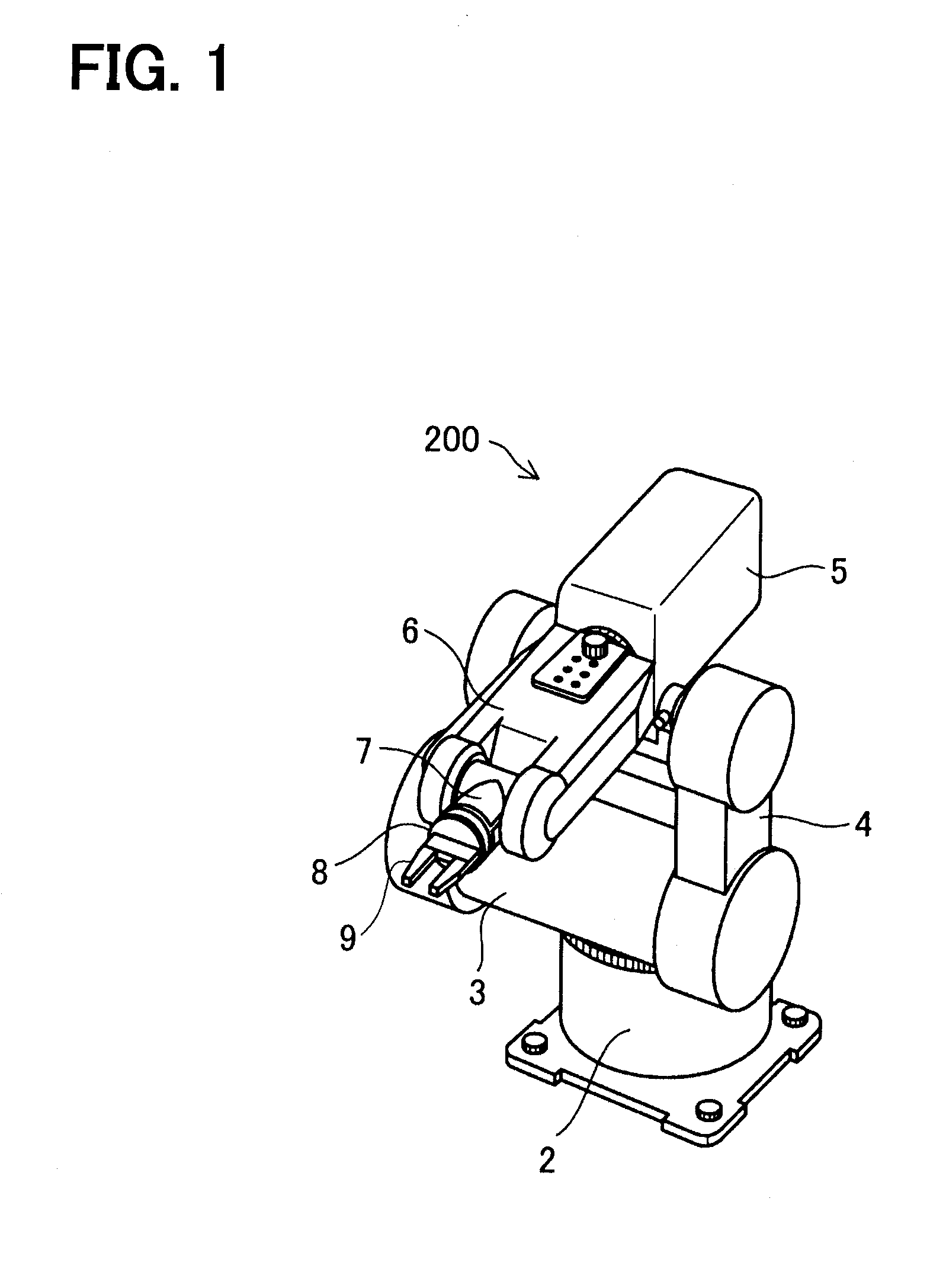
[0018]FIG. 1 is a descriptive view showing a schematic structure of a robot 200 according to an embodiment of the present disclosure. The robot 200 of the present embodiment is an industrial six-axis vertical articulated robot.

[0019]The robot 200 includes: a base 2 that is fixed to a horizontal surface at an installation location (site), such as a factory; a shoulder 3 that is supported by the base 2 in a manner that enables rotation of the shoulder 3 about a first axis, which extends in a vertical direction; a lower arm 4 that has a lower end portion supported by the shoulder 3 in a manner that enables rotation of the lower arm 4 about a second axis, which extends in a horizontal direction; a rear upper arm 5 that is supported by a distal end portion of the lower arm 4 in a manner that enables rotation of the rear upper arm 5 about a third axis, which extends in the horizontal direction; a front upper arm 6 that is supported by the rear upper arm 5 in a manner that enables rotation...


PUM


Abstract

A plurality of intermediate shafts, which are placed between an input shaft and an output shaft, respectively includes a large diameter gear and a small diameter gear. The large diameter gear of each intermediate shaft is meshed with a corresponding one of an input gear of the input shaft or the small diameter gear of another one of the intermediate shafts located on the input shaft side. The small diameter gear of each intermediate shaft is meshed with a corresponding one of an output shaft of the output shaft or the large diameter gear of another one of the intermediate shafts located on the output shaft side.

Description

CROSS REFERENCE TO RELATED APPLICATION[0001]The present application is based on and incorporates herein by reference Japanese Patent Application No. 2014-16320 filed on Jan. 31, 2014.TECHNICAL FIELD[0002]The present disclosure relates to an actuator.BACKGROUND ART[0003]As recited in, for example, the Patent Literature 1, a device, which has three geared shafts, i.e., a sensing-subject shaft, a first shaft and a second shaft, is known as a rotational angle sensing device used in, for example, an actuator. In this device, a gear, which is meshed with a gear of the sensing-subject shaft, and a gear, which is meshed with a gear of the second shaft, are provided to the first shaft. A rotational angle of the sensing-subject shaft is computed based on a combination of rotational angles respectively sensed at the first shaft and the second shaft, which are other than the sensing-subject shaft.CITATION LISTPatent LiteraturePatent Literature 1: JP2004-61428ASUMMARY OF THE INVENTION[0004]Howev...

Claims


Application Information

Patent Timeline
IPC IPC(8): B25J9/10G01D5/14H02K7/14H02K7/116H02K11/215H02K11/33G01D5/04H02K7/00
CPCB25J9/102G01D5/04G01D5/145H02K7/14H02K7/116H02K11/215H02K11/33H02K7/003
Inventor KATO, YUSUKE
Owner DENSO WAVE INC
Why Eureka
Try Eureka