Shaping system, shaping object manufacturing method, and data processing method

a technology of shaping object and manufacturing method, applied in the direction of manufacturing tools, instruments, electrographic processes, etc., can solve the problems of image formation accuracy and stacking accuracy not being guaranteed, image formation accuracy and stacking accuracy may decline, etc., to achieve the effect of improving the quality and accuracy of shaping objects

Inactive Publication Date: 2017-01-05
CANON KK
View PDF0 Cites 36 Cited by
  • Summary
  • Abstract
  • Description
  • Claims
  • Application Information

AI Technical Summary

Benefits of technology

[0011]According to the present invention, in a shaping system adopting a method involving independently forming images of respective layers and sequentially stacking the images to obta

Problems solved by technology

In particular, in a case where a shaping operation is suspended midway through the shaping of a shaping object, there is a concern that image formation accuracy may decline when restarting the shaping operation.
This becomes a major issue with stacking methods involving independently forming images of respective layers and sequentially stacking the images as is the case of the apparatuses according to Japanese Patent Application Laid-open No.
H10-224581 and Japanese Patent Application Laid-open No. 2003-0

Method used


Image

  • Shaping system, shaping object manufacturing method, and data processing method
  • Shaping system, shaping object manufacturing method, and data processing method
  • Shaping system, shaping object manufacturing method, and data processing method

Examples


embodiment

Configuration of Shaping System

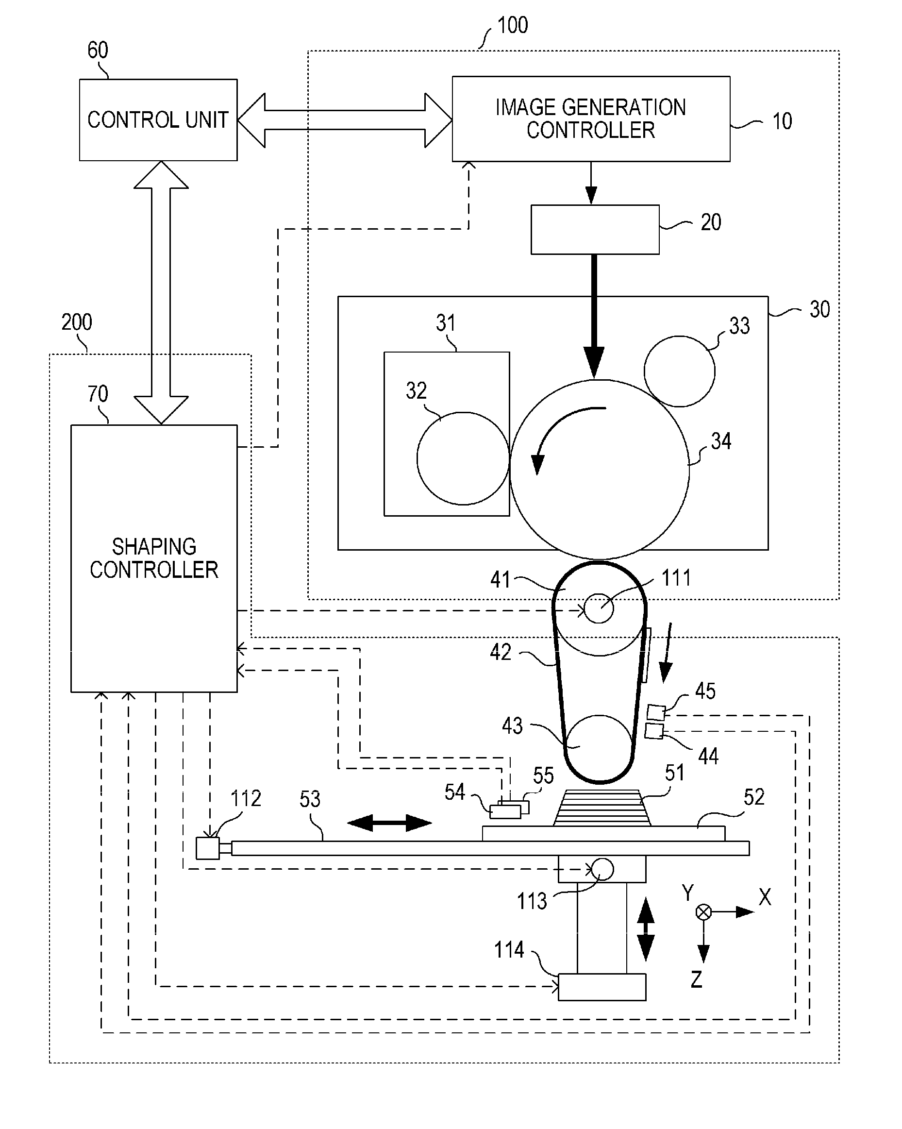
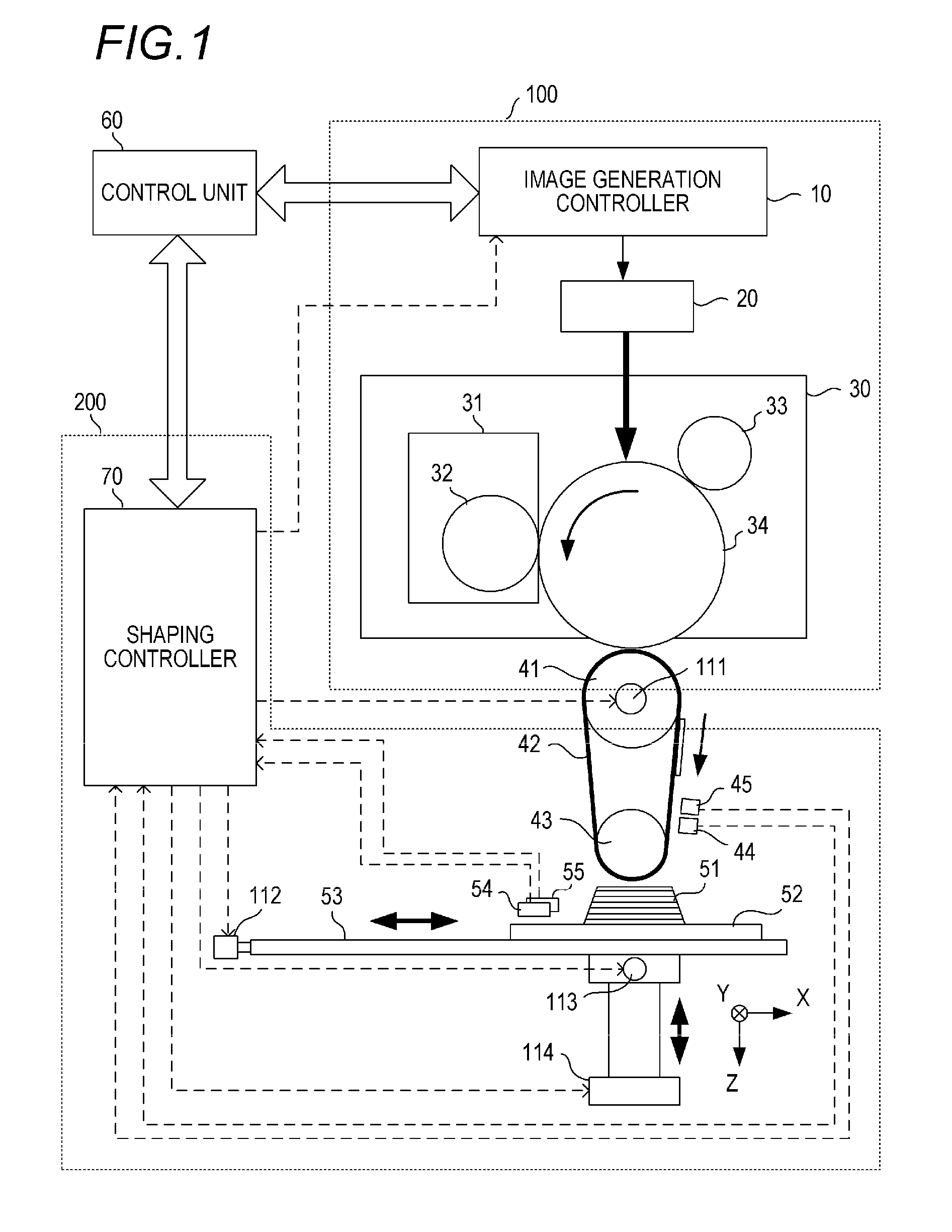
[0027]A configuration of a shaping system according to an embodiment of the present invention will be described with reference to FIG. 1. FIG. 1 is a diagram schematically showing a configuration of a shaping system according to an embodiment.

[0028]A shaping system is a system which creates a stereoscopic shaping object by stacking a large number of thin films according to a manufacturing method using a stack shaping method. This system is also referred to as an additive manufacturing (AM) system, 3D printer, rapid prototyping (RP) system, and the like.

[0029]The shaping system according to the present embodiment roughly includes a material layer forming section 100, a shaping unit 200, and a control unit 60. The material layer forming section 100 is a component which forms a material layer made of a shaping material based on slice data of each layer.

[0030]The material layer forming section 100 is constituted by an image generation controller 10, a lase...


PUM

PropertyMeasurementUnit
Shapeaaaaaaaaaa
Threshold limitaaaaaaaaaa

Abstract

A shaping system that fabricates a shaping object by stacking a material layer formed based on slice data, the shaping system comprises a control section which controls operations of respective sections of the shaping system. The control section controls the respective sections so that, at a prescribed timing, a marker is formed and stacked on a top surface of a marker support body, image distortion information is acquired from a position of the marker as detected by a marker position detecting section, and a correction process for correcting the slice data is executed.

Description

BACKGROUND OF THE INVENTION[0001]Field of the Invention[0002]The present invention relates to a shaping system, a shaping object manufacturing method, and a data processing method.[0003]Description of the Related Art[0004]Shaping systems which form a three-dimensional shaping object by stacking a large number of layers are drawing attention. Stack shaping technology of this type is referred to as additive manufacturing (AM), three-dimensional printing, rapid prototyping, and the like. Various shaping methods are proposed to implement the stack shaping technology. Japanese Patent Application Laid-open No. H10-224581 and Japanese Patent Application Laid-open No. 2003-053846 disclose shaping methods utilizing an electrophotographic process while US Patent Application Publication No. 2009 / 0060386 (Specification) discloses a laser sintering method.SUMMARY OF THE INVENTION[0005]In a shaping system, a shape accuracy of a sectional image of each layer (image formation accuracy) and a positi...

Claims


Application Information

Patent Timeline
IPC IPC(8): B29C67/00
CPCB29C67/0074B29C67/0085B33Y50/00B33Y10/00B33Y30/00B29C67/0088B29C64/141B29C64/147B29C64/393G03G15/224
Inventor SOBUE, IKUOSAKURAI, SHIGEKISUZUKI, NORIYUKI
Owner CANON KK
Why Eureka
Try Eureka