

Voltage monitoring module and voltage monitoring system
a voltage monitoring module and voltage monitoring technology, applied in the direction of measurement devices, instruments, transportation and packaging, etc., can solve the problem of the frequency of voltage measurement of each battery cell decreasing
- Summary
- Abstract
- Description
- Claims
- Application Information
AI Technical Summary
Benefits of technology
Problems solved by technology
Method used
Image

Examples
first embodiment
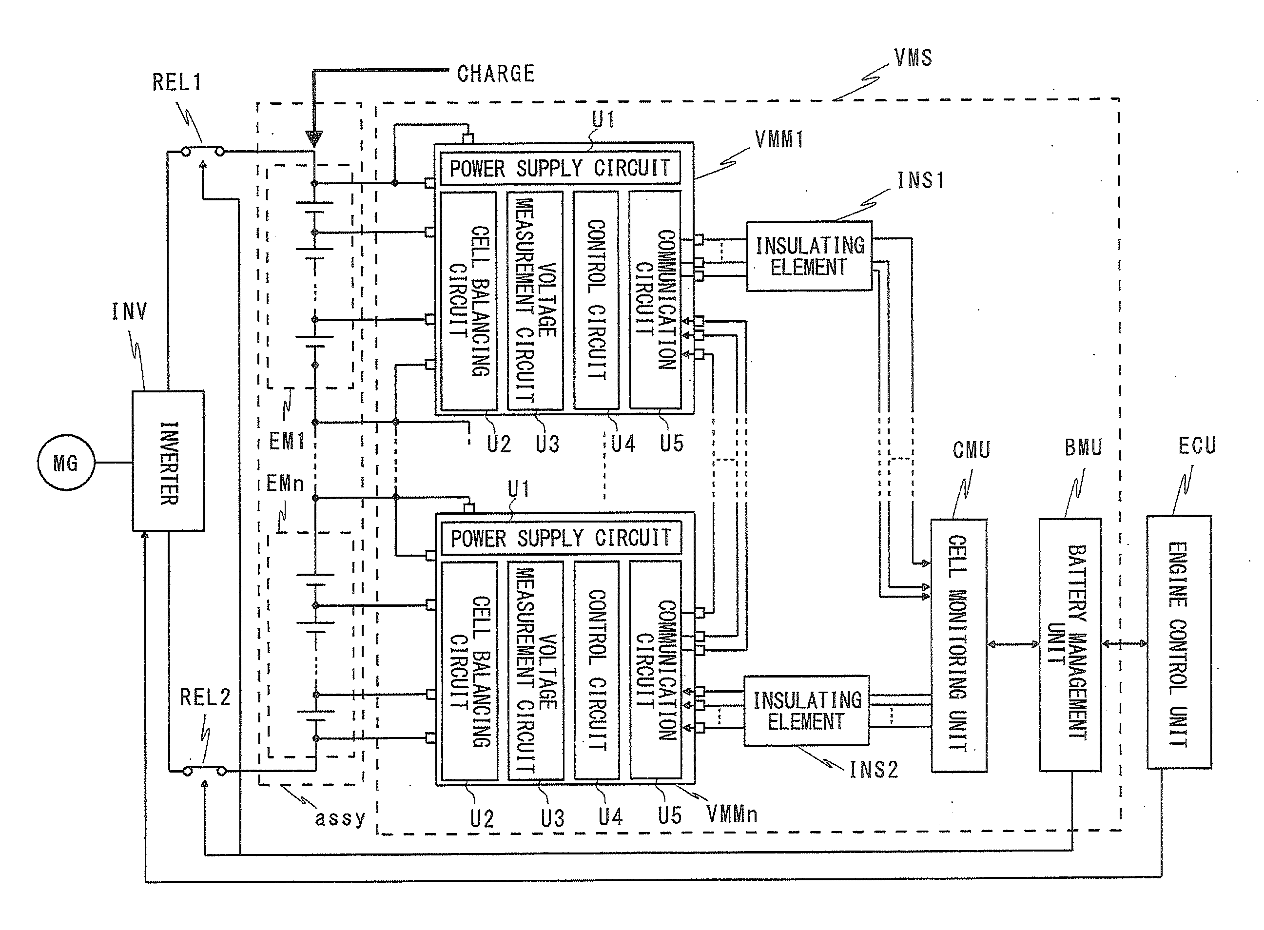
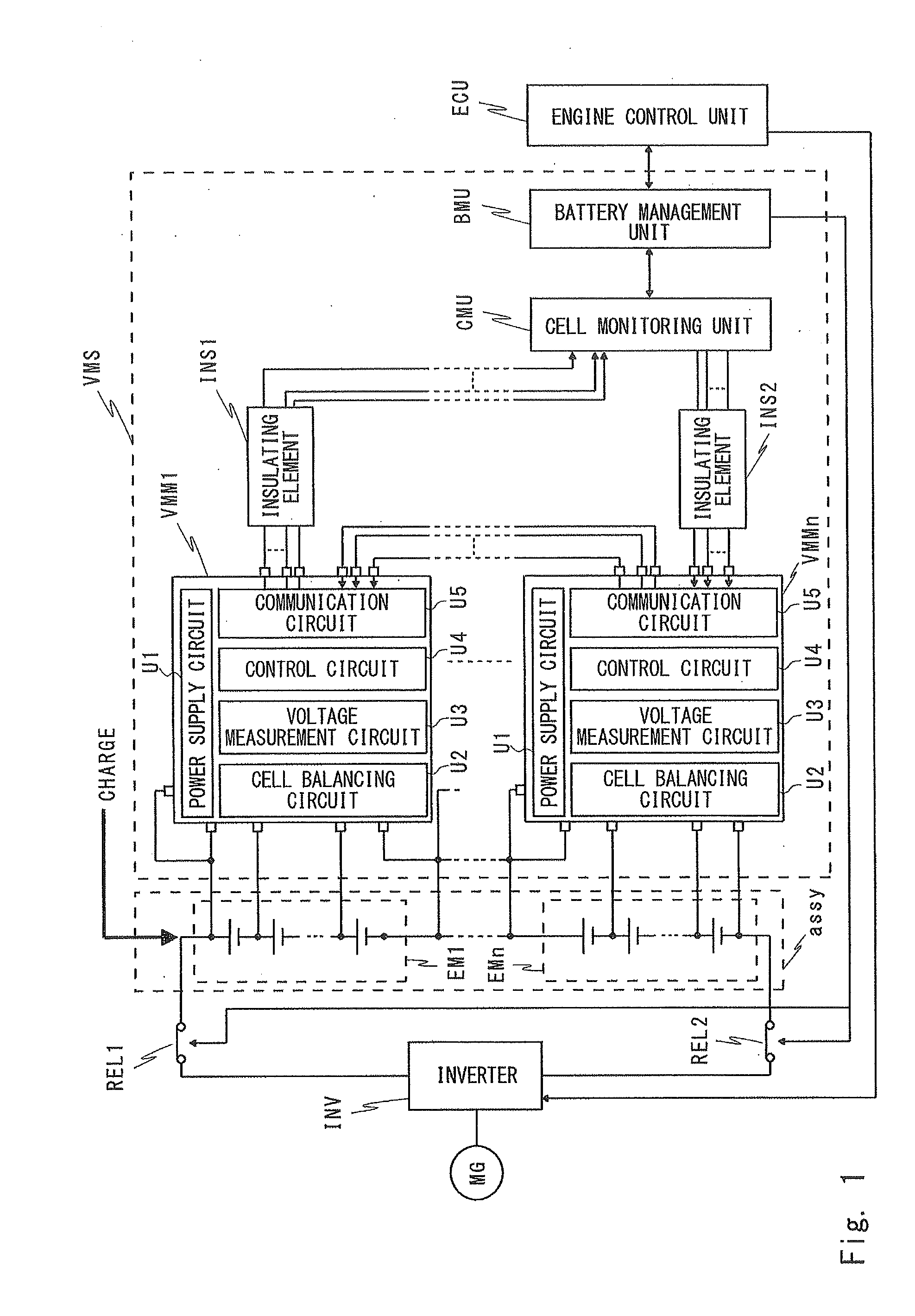
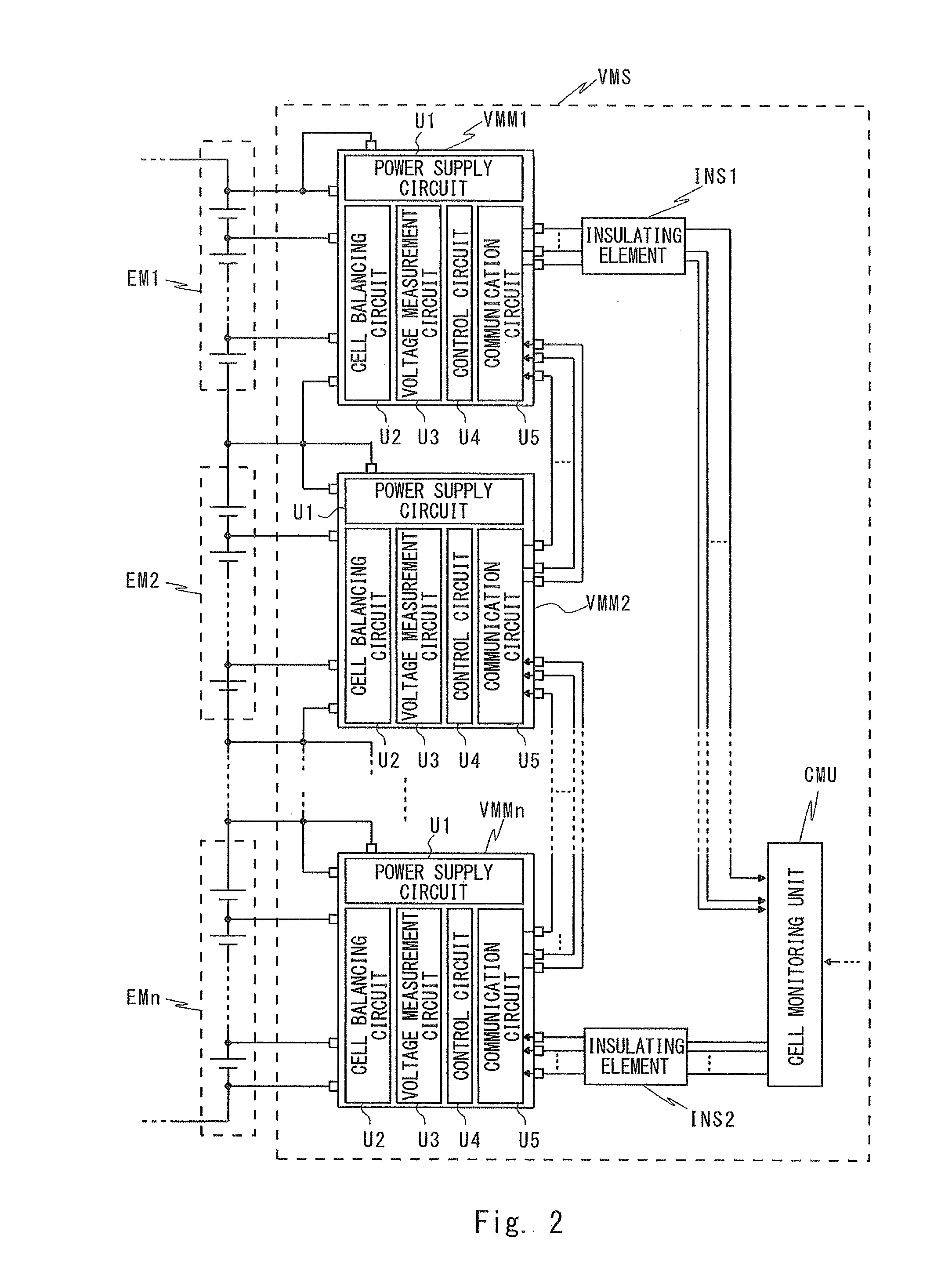
[0084]A voltage monitoring module 100 according to a first embodiment will be described below. The voltage monitoring module 100 corresponds to each of the voltage monitoring modules VMM1 to VMMn shown in FIGS. 1 to 3. FIG. 6 is a circuit diagram showing a configuration of a main part of the voltage monitoring module 100 according to the first embodiment. In the voltage monitoring module 100, a voltage measurement circuit VMC1 corresponds to the voltage measurement circuit VMC of the voltage monitoring modules VMM1 to VMMn. For simplification of the explanation, FIG. 6 illustrates the components necessary to understand the configuration and operation of the voltage monitoring module 100.
[0085]As compared with the voltage monitoring module VMM1 shown in FIG. 3, the voltage monitoring module 100 has a configuration in which protection diodes D1 to Dm and a disconnection detection circuit 10 are added to the voltage measurement circuit VMC1. Note that in FIG. 6, the illustration of eac...
second embodiment
[0106]Next, a voltage monitoring module 200 according to the second embodiment will be described. The voltage monitoring module 200 is a modified example of the voltage monitoring module 100 according to the first embodiment. FIG. 13 is a circuit diagram showing a configuration of a main part of the voltage monitoring module 200 of the second embodiment. In the voltage monitoring module 200, a voltage measurement circuit VMC2 corresponds to the voltage measurement circuit VMC1 of the voltage monitoring module 100. For simplification of the explanation, FIG. 13 illustrates the components necessary to understand the configuration and operation of the voltage monitoring module 200. Specifically, FIG. 13 illustrates only the circuit elements and circuit blocks associated with the input terminals V_m to V_m+1.
[0107]The voltage monitoring module 200 has a configuration in which the disconnection detection circuit 10 of the voltage monitoring module is replaced with a disconnection detecti...
third embodiment
[0121]Next, a voltage monitoring module 300 according to a third embodiment will be described. The voltage monitoring module 300 is a modified example of the voltage monitoring module 100 according to the first embodiment. The voltage monitoring module 300 differs from the voltage monitoring module 100 in that the voltage monitoring module 300 has a self-diagnosis function of a disconnection detection circuit.
[0122]FIG. 19 is a circuit diagram showing a configuration of a main part of the voltage monitoring module 300 according to the third embodiment. For simplification of the explanation, FIG. 19 illustrates the components necessary to understand the configuration and operation of the voltage monitoring module 300. Specifically, FIG. 19 illustrates only circuit elements and circuit blocks associated with the input terminals V_1 to V_3. In the voltage monitoring module 300, a voltage measurement circuit VMC3 corresponds to the voltage measurement circuit VMC1 of the voltage monitor...
PUM
 Abstract
Description
Claims
Application Information