Wide area sensing system, in-flight detection method, and non-transitory computer readable medium storing program of wide area sensing system

Active Publication Date: 2017-01-05
KK TOPCON
View PDF3 Cites 29 Cited by
  • Summary
  • Abstract
  • Description
  • Claims
  • Application Information

AI Technical Summary

Benefits of technology

[0009]An object of the present invention is, therefore, to provide a wider ar

Problems solved by technology

However, in the conventional apparatus, since the tractor needs to move along the both sides of the crops to be detected, the area where the conventional apparatus can detect the growth sta

Method used


Image

  • Wide area sensing system, in-flight detection method, and non-transitory computer readable medium storing program of wide area sensing system
  • Wide area sensing system, in-flight detection method, and non-transitory computer readable medium storing program of wide area sensing system
  • Wide area sensing system, in-flight detection method, and non-transitory computer readable medium storing program of wide area sensing system

Examples


embodiment 1

[0023]First, the schematic structure of a wide area sensor system 10 according to a first embodiment of the wide area sensor system of the present invention will be described with reference to FIGS. 1 to 8. The wide area sensor system 10 performs an in-flight detection method as an embodiment of the wide area sensor system of the present invention and includes a program as an embodiment of the program according to the present invention. FIG. 7 schematically shows an example of how high speed sensing Sf is performed over a farm land FL, and FIG. 8 schematically shows an example of how low speed sensing Ss is performed on the farm land FL. Note that these examples do not necessarily comply with actual aspects.

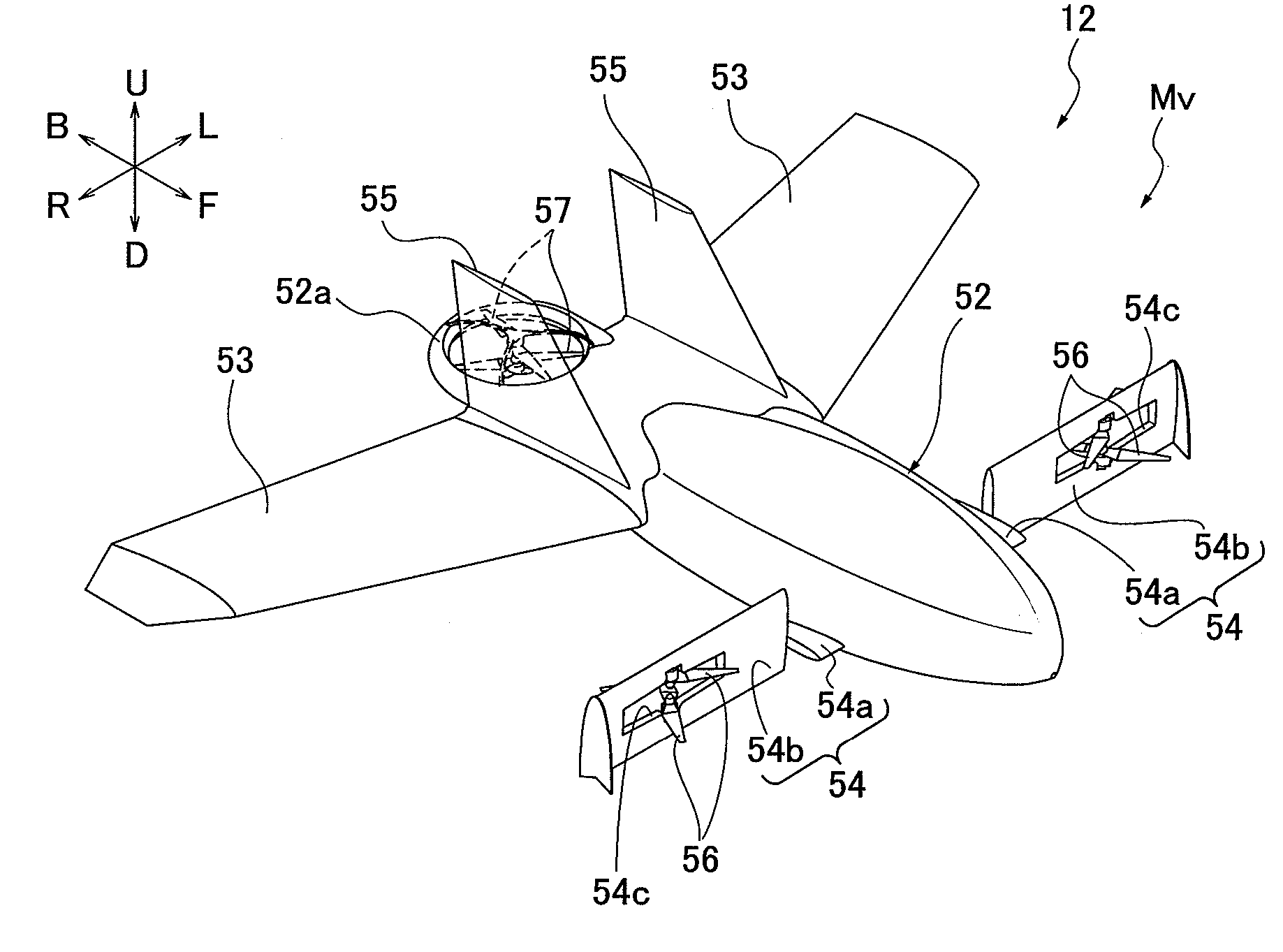
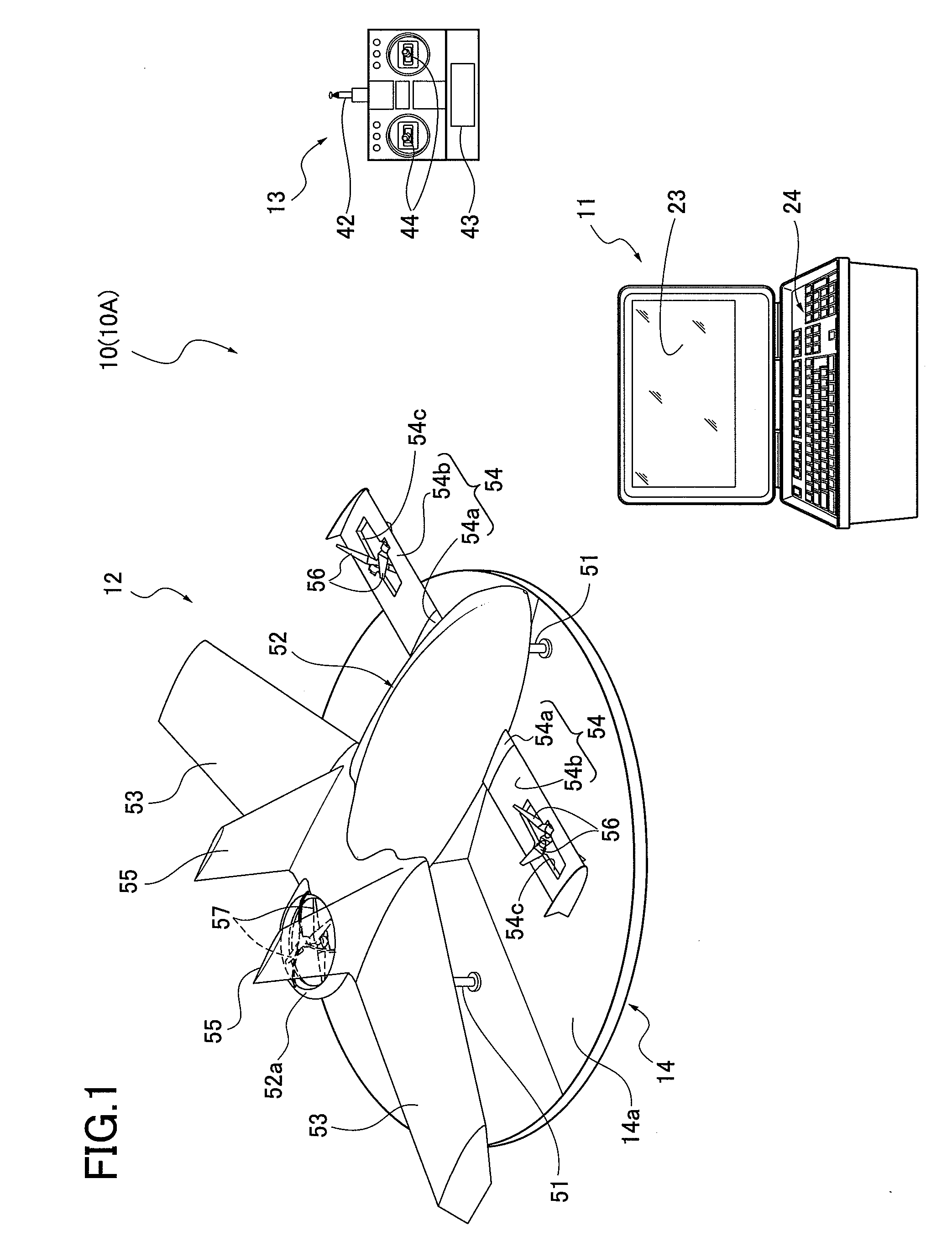
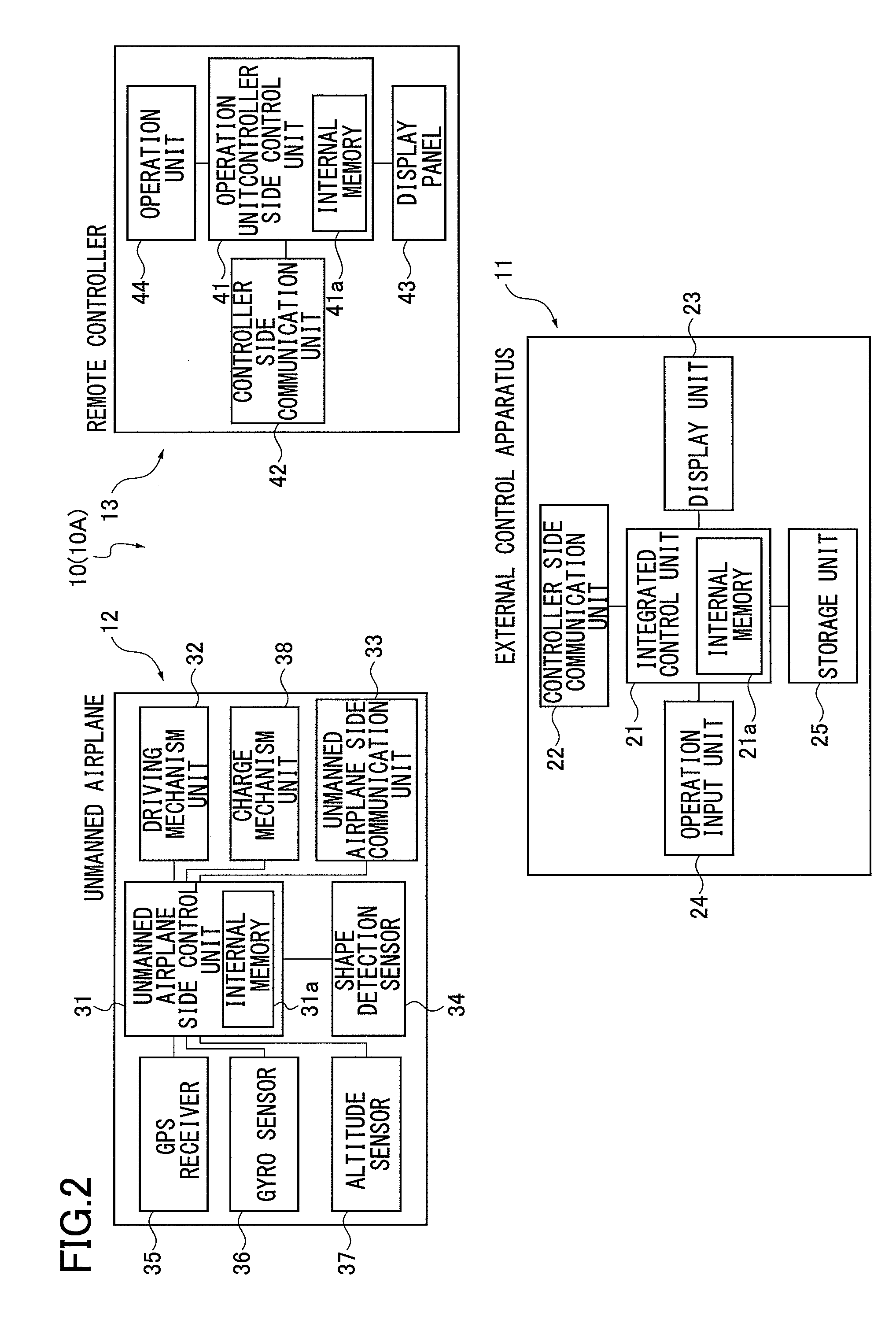
[0024]The wide area sensor system 10 according to the first embodiment of the present invention includes, an external control apparatus 11, an unmanned airplane 12, a remote controller 13, and a dock 14, as shown in FIG. 1. The wide area sensor system 10 detects the state of a de...

embodiment 2

[0096]Next, a wide area sensor system 10A as a wide area sensor system according to a second embodiment of the invention will be described with reference to FIGS. 9 to 11. The wide area sensor system 10A according to the second embodiment is an example in which sensing processing in in-flight detection processing is different from that in the wide area sensor system 10 in the first embodiment. The basic structure and operation of the wide area sensor system 10A according to the second embodiment are the same as in the wide area sensor system 10 according to the first embodiment. Accordingly, FIGS. 1 and 2 are used to show the entire structure. Note that the same components are given the same reference symbols, and detailed descriptions are omitted.

[0097]The wide area sensor system 10A according to the second embodiment uses a 360 degree camera, a laser scanning device, and a noncontact type temperature sensor as the state detection sensor 34 (see FIG. 1). In addition, since the wide...


PUM


Abstract

A wide area sensor system includes an unmanned airplane being switchable between an airplane mode for high speed flight and a VTOL mode for low speed flight, a state detection sensor provided in the unmanned airplane, the state detection sensor being driven to detect a state of a detection target, and an external control apparatus that controls flight of the unmanned airplane and driving of the state detection sensor. The external control apparatus performs high speed sensing by driving the state detection sensor while performing the high speed flight of the unmanned airplane in the airplane mode. The control apparatus performs low speed sensing by driving the state detection sensor while performing the low speed flight of the unmanned airplane in the VTOL mode.

Description

CROSS-REFERENCE TO RELATED APPLICATION[0001]The present application is based on and claims priority to Japanese patent application No. 2015-131667, filed Jun. 30, 2015, the disclosure of which is hereby incorporated by reference herein in its entirety.BACKGROUND[0002]Technical Field[0003]The present invention relates to a wide area sensor system, in-flight detection method, and a non-transitory computer readable medium storing program for detecting a state of a detection target ranging widely.[0004]Description of Related Art[0005]In the agricultural field, for example, it has been important to yield crops efficiently by accurately grasping the growth state of the crops to improve the yield of farm crops. In order to achieve that, there is a known technique that acquires a reflected measurement light from crops (plants (the target to be detected), determines a reflectivity of the measurement light against the crops, and detects the growth state of the crops based on the determined re...

Claims


Application Information

Patent Timeline
IPC IPC(8): G05D1/10G05D1/00B64C39/02
CPCB64C13/20B64C29/0033B64C39/024B64U10/25B64U2101/00B64U2101/30B64U2201/20B64U10/10B64C19/00B64C27/30B64C27/26G05D1/0088B64C27/00G05D1/0011G05D1/102
Inventor TANAHASHI, ATSUSHI
Owner KK TOPCON
Why Eureka
Try Eureka