Supercharge Your Innovation With Domain-Expert AI Agents!

Ultra low NOX insulating burner without collar

a burner and low nox technology, applied in the field of burners, can solve problems such as damage and/or deformation of partition plates, and achieve the effect of limited heat transfer between the flange and the adjacent componen

Inactive Publication Date: 2017-01-12
CARRIER CORP
View PDF7 Cites 5 Cited by
  • Summary
  • Abstract
  • Description
  • Claims
  • Application Information

AI Technical Summary

Benefits of technology

The patent describes a burner design that includes a flange with openings that allow fluid to flow through without particles of debris. The flange is positioned at the outlet end of the burner tube and is made from a different material than the burner tube. The flange can be removably or fixedly coupled to the burner tube. The technical effect of this design is that it allows for limited heat transfer between the flange and the adjacent component, which can improve the efficiency of the burner.

Problems solved by technology

Due to the highly conductive nature of the flange, the heat of the flame is transferred to the partition plate via the flanges, resulting in damage and / or deformation of the partition plate.

Method used


Image

  • Ultra low NOX insulating burner without collar
  • Ultra low NOX insulating burner without collar
  • Ultra low NOX insulating burner without collar

Examples


Embodiment Construction

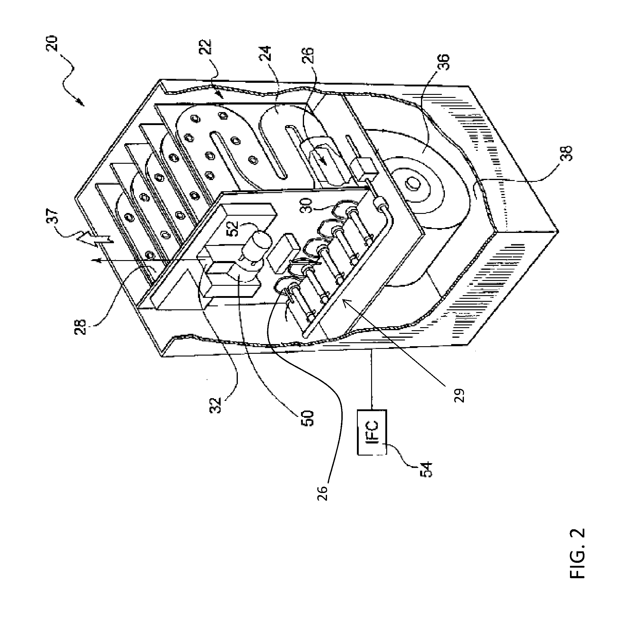
[0033]Referring now to FIG. 2, an improved furnace 20 is illustrated. The furnace 20 may include a heat exchanger 22 having a plurality of individual heat exchanger coils 24. The heat exchanger coils 24, which may be metallic conduits, may be provided in a serpentine fashion to provide a large surface area in a small overall volume of space. Each heat exchanger coil 24 includes an inlet 26 and outlet 28. A burner assembly 29 includes a burner 30 operatively associated with each inlet 26, and a vent 32 operatively associated with each outlet 28. The burner assembly 29 introduces a flame and combustion gases (not shown) into the heat exchanger coil 24, while vent 32 releases the combustion gases to atmosphere (through a flue or the like) after the heat of the flame and combustion gases is extracted by the heat exchanger 22.

[0034]In order to extract the heat, a blower motor 36 may be provided to create a significant air flow across the heat exchanger coils 24. As the air circulates acr...


PUM


Abstract

A burner comprising is provided including a burner tube formed at least partially from a first material having a plurality of openings. The plurality of openings are sized to allow a fluid but not particles of debris contained within the fluid to flow there through. A flange extends outwardly from a portion of the burner tube and is receivable within an embossment formed in an adjacent component. The flange is formed from a second material having a plurality of openings such that heat transfer between the flange and the adjacent component is limited.

Description

CROSS-REFERENCE TO RELATED APPLICATION[0001]This application claims the benefit of U.S. provisional patent application Ser. No. 62 / 190,576 filed Jul. 9, 2015, the entire contents of which are incorporated herein by reference.BACKGROUND[0002]The subject matter disclosed herein relates to heating systems. More specifically, the subject disclosure relates to burners for residential and commercial heating systems.[0003]Heating systems, in particular furnaces, include one or more burners for combusting a fuel such as natural gas. Hot flue gas from the combustion of the fuel proceeds from the burner and through a heat exchanger. The hot flue gas transfers thermal energy to the heat exchanger, from which the thermal energy is then dissipated by a flow of air driven across the heat exchanger by, for example, a blower.[0004]A typical prior art construction is shown in FIG. 1. A burner 100 is located external to a heat exchanger 102. The burner 100, often referred to as an inshot burner 100, ...

Claims


Application Information

Patent Timeline
Patent Type & Authority Applications(United States)
IPC IPC(8): F23D14/68F23D14/02
CPCF23D14/02F23D14/68F23L17/005F23D14/105F23D2203/1012F23D2203/103
Inventor GARLOCH, DUANE D.SHAW, ROBERTKAMM, NICHOLAS
Owner CARRIER CORP
Features
  • R&D
  • Intellectual Property
  • Life Sciences
  • Materials
  • Tech Scout
  • Unparalleled Data Quality
  • Higher Quality Content
  • 60% Fewer Hallucinations
Learn More