Pressure sensor and manufacturing method therefor

a manufacturing method and sensor technology, applied in the field of sensors, can solve the problems of poor temperature drift characteristic, non-accuracy pressure detection, and piezo-resistive material

Active Publication Date: 2017-01-12
CSMC TECH FAB2 CO LTD
View PDF4 Cites 1 Cited by
  • Summary
  • Abstract
  • Description
  • Claims
  • Application Information

AI Technical Summary

Benefits of technology

[0006]The pressure sensor as mentioned adopts an optical method to transfer a deformation value of the detecting diaphragm into a light intensity, and employs the light detector to transfer the light intensity to an electrical signal and obtains the pressure by virtue of performing a calculation, thus effectively addressing issues of a temperature drift characteristic and an electromagnetic interference of the piezo-resistance pressure sensor itself.

Problems solved by technology

However, the piezo-resistive material is naturally susceptible to the change of external temperature, the temperature drift characteristic is poor.
In the complicated electromagnetic environment, the circuit mode adopting the wheatstone bridge is vulnerable to interference, thus leading to a non-accuracy pressure detection.

Method used


Image

  • Pressure sensor and manufacturing method therefor
  • Pressure sensor and manufacturing method therefor
  • Pressure sensor and manufacturing method therefor

Examples


Embodiment Construction

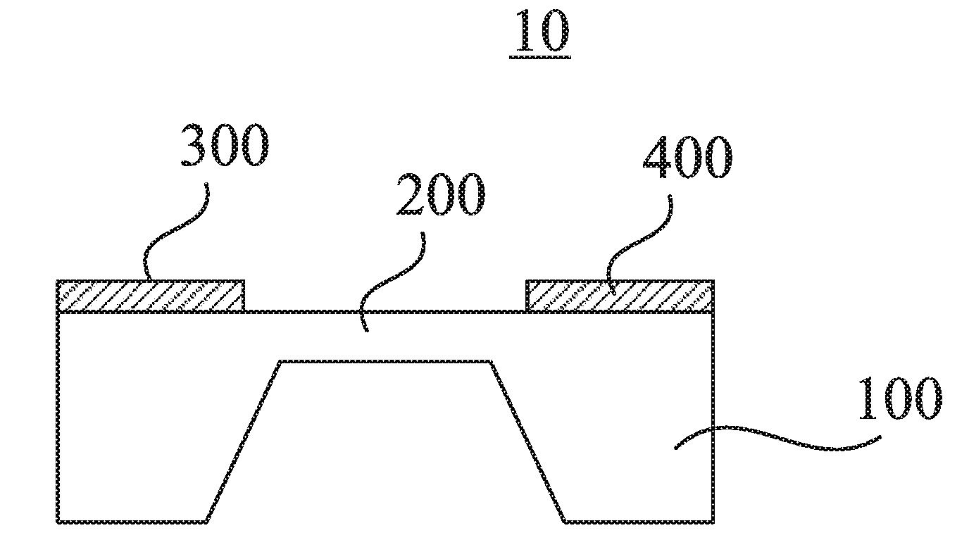
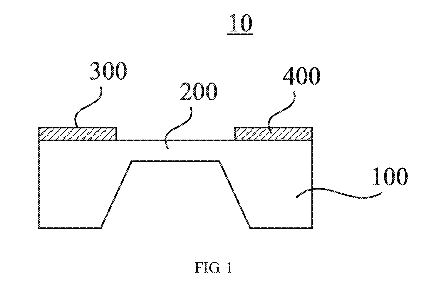
[0011]As shown in FIG. 1, a pressure sensor 10 according to one embodiment includes a detecting diaphragm 200, a light emitter 300, and a light detector 400.

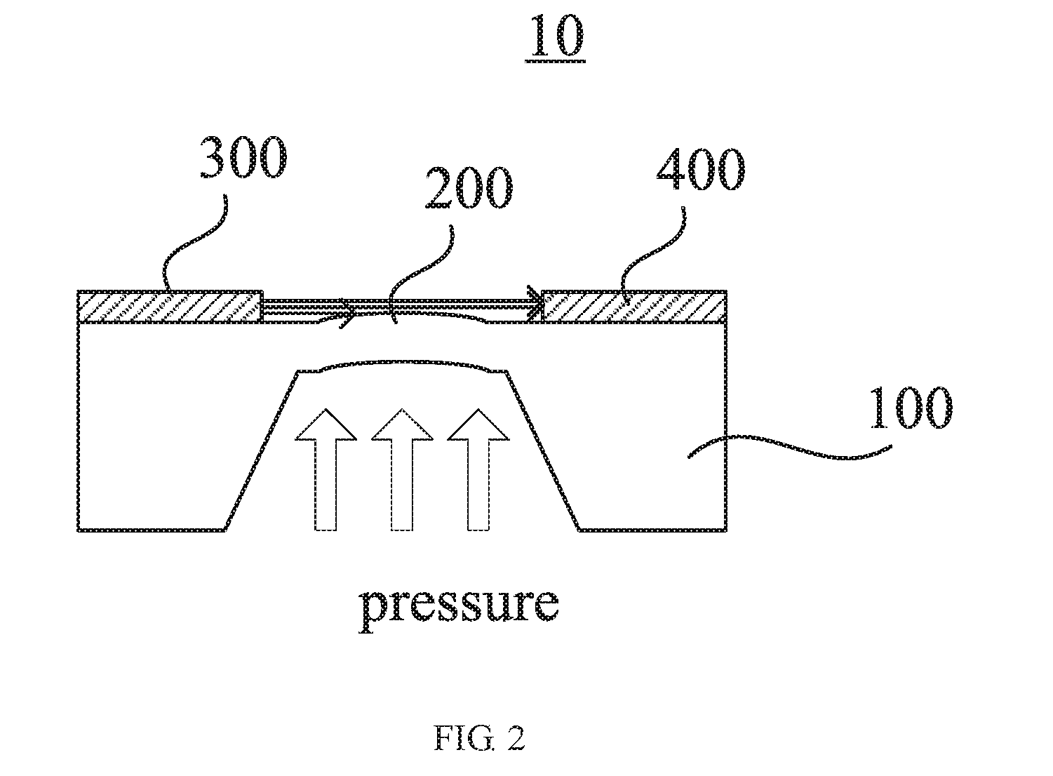
[0012]Referring to FIG. 2, the detecting diaphragm 200 is configured to detect a pressure applied to a surface of the detecting diaphragm 200 and generates a protrusion deformation in response to the pressure. Generally, a selection of the material forming the detecting diaphragm and a size of the detecting diaphragm enable the size of the pressure to be proportional to a protruding value of the detecting diaphragm 200. In the illustrated embodiment, the detecting diaphragm 200 is a silicon structure which is integrally formed with the silicon substrate 100. A thickness of the detecting diaphragm 200 is designed to be 5 microns to 100 microns according to a greater pressure value. The protruding value of the detecting diaphragm 200 is equal to or less than 30 microns.

[0013]Referring to FIG. 3, the light emitter 300 and the light...


PUM

PropertyMeasurementUnit
thicknessaaaaaaaaaa
diameteraaaaaaaaaa
diameteraaaaaaaaaa

Abstract

A pressure sensor (10) comprising: a detection film (200) which is arranged on a silicon substrate (100) and is used for detecting a pressure which is applied to the surface of the detection film and generating a bulge deformation which adapts to the size of the pressure; an optical transmitter (300) and an optical detector (400) which are arranged on the silicon substrate (100), are located on a plane which is parallel to a plane where the detection film (200) is located, and are oppositely arranged at two sides of the detection film (200); and a pressure calculation module which is connected to the optical detector (400) and is used for acquiring detected light intensity data, and calculating a pressure value according to the light intensity data.

Description

FIELD OF THE INVENTION[0001]The invention relates to a technical field of sensors, and more particularly relates to a pressure sensor and a manufacturing method of the pressure sensor.BACKGROUND OF THE INVENTION[0002]The conventional piezo-resistive MEMS pressure sensor takes advantage of the piezo-resistive characteristic of silicon material to fabricate the four-bridge arm resistance of wheatstone bridge. It detects the pressure by virtue of the voltage change caused by the resistance change which is generated by pressure. However, the piezo-resistive material is naturally susceptible to the change of external temperature, the temperature drift characteristic is poor. In the complicated electromagnetic environment, the circuit mode adopting the wheatstone bridge is vulnerable to interference, thus leading to a non-accuracy pressure detection.SUMMARY OF THE INVENTION[0003]Accordingly, it is necessary to provide a pressure sensor which can effectively address problems of temperature...

Claims


Application Information

Patent Timeline
Patent Type & Authority Applications(United States)
IPC IPC(8): G01L1/24G01L1/04
CPCG01L1/04G01L1/242G01L7/086
Inventor QIAN, DONGBIAO
Owner CSMC TECH FAB2 CO LTD
Why Eureka
Try Eureka