Magnetic susceptor to baseplate seal

a susceptor and magnetic technology, applied in the field of magnetic susceptor and baseplate sealing, can solve the problems of particle generation, defect generation of processed substrates, particle generation,

Active Publication Date: 2017-01-12
ASM IP HLDG BV
View PDF42 Cites 305 Cited by
  • Summary
  • Abstract
  • Description
  • Claims
  • Application Information

AI Technical Summary

Benefits of technology

[0007]Embodiments of the present disclosure relate to a reaction system for processing substrates including: a susceptor configured to hold a substrate, a baseplate of a reaction region, at least one susceptor magnet, and at least one baseplate magnet. An interaction of the at least one susceptor magnet and the at least one baseplate magnet creates a repelling force to maintain a gap between the susceptor and the baseplate.

Problems solved by technology

In addition, the gap is necessary as direct physical contact between the susceptor and the baseplate could result in particle generation.
Particle generation is problematic as the smallest particles can contaminate and potentially cause defects in the processed substrate.
Over time, continued processing can lead to a deposit of reactive materials on and around the pads of the susceptor.
Similar to the particle generation, a deposition build-up can cause issues of contamination and defects in the processed substrate.

Method used


Image

  • Magnetic susceptor to baseplate seal
  • Magnetic susceptor to baseplate seal
  • Magnetic susceptor to baseplate seal

Examples


Embodiment Construction

[0027]Although certain embodiments and examples are disclosed below, it will be understood by those in the art that the invention extends beyond the specifically disclosed embodiments and / or uses of the invention and obvious modifications and equivalents thereof. Thus, it is intended that the scope of the invention disclosed should not be limited by the particular disclosed embodiments described below.

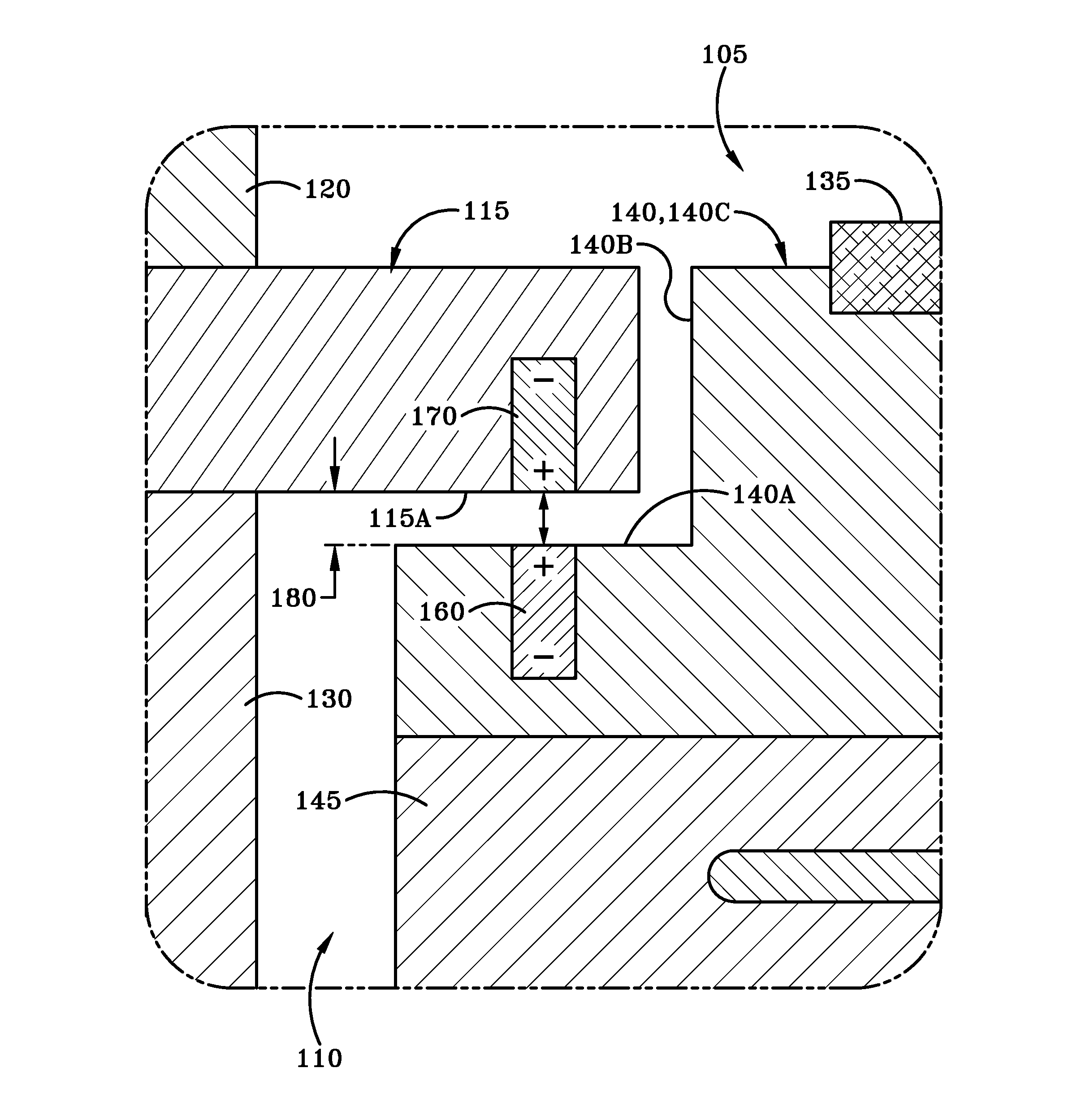
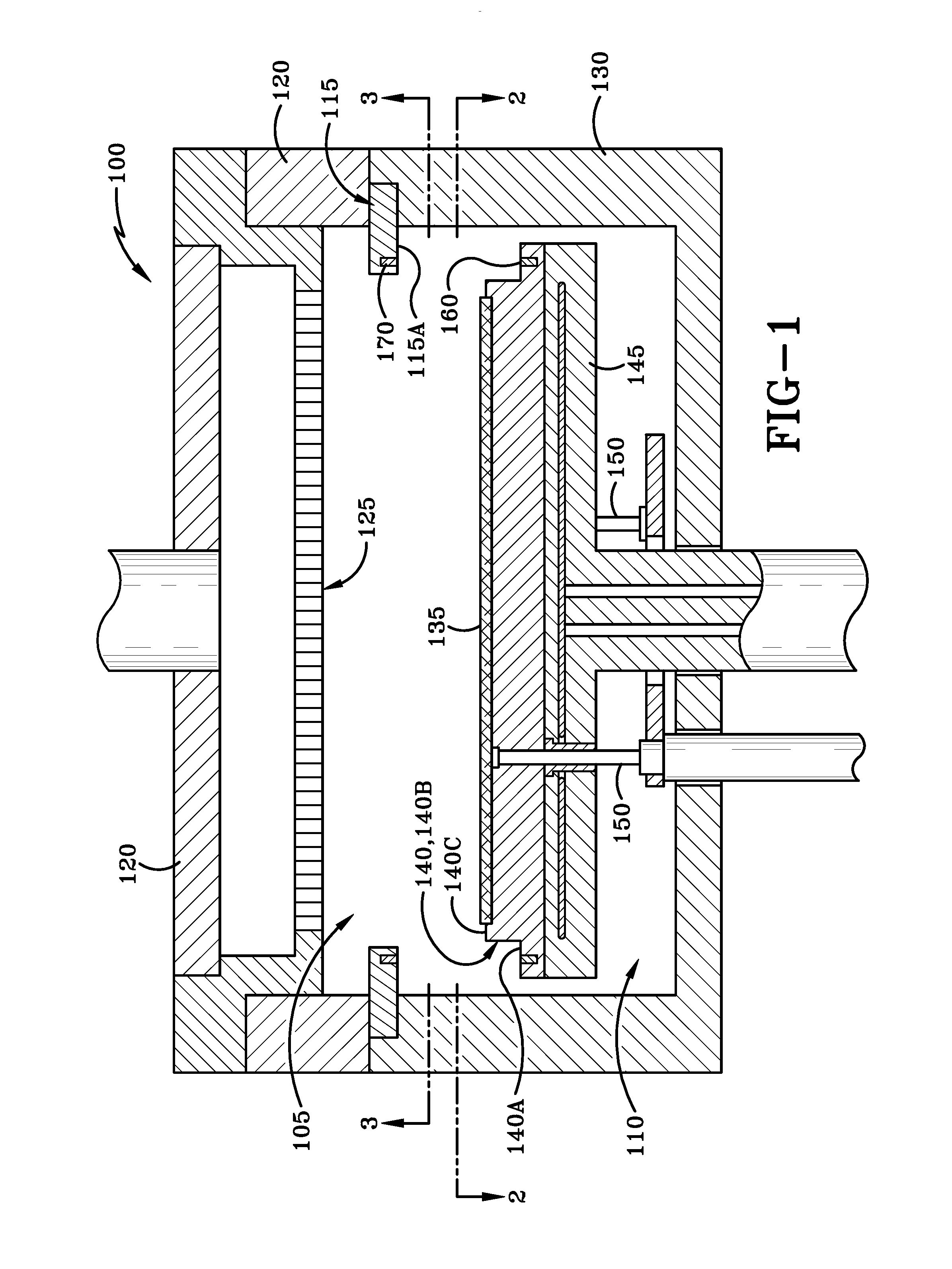
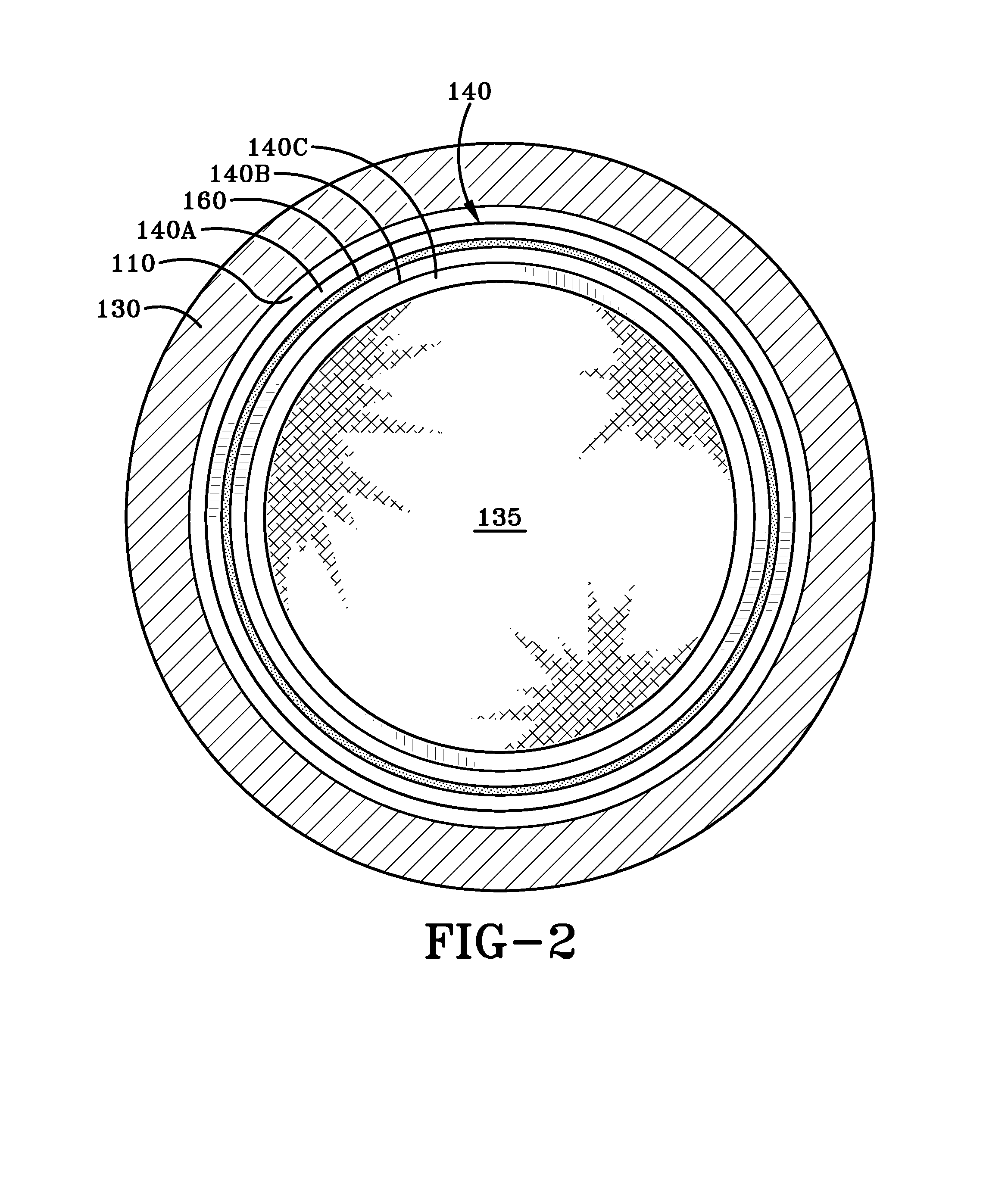
[0028]The embodiments of this invention are directed to reaction systems that are used to process substrates. The reaction systems include a susceptor for holding a substrate. As used herein, a “substrate” refers to any material having a surface onto which material can be deposited. The reaction systems also include a reaction region defined in part by a baseplate. The susceptor will be loaded with the substrate and then bring the substrate into the reaction region for processing. During processing, deposition of materials may take place on the substrate. In embodiments of the inventio...


PUM

PropertyMeasurementUnit
heightaaaaaaaaaa
heightaaaaaaaaaa
heightaaaaaaaaaa

Abstract

A reaction system for processing semiconductor substrates is disclosed. In particular, the invention discloses an arrangement of a susceptor and a baseplate for when a substrate is placed into a reaction region. Magnets are embedded into the susceptor and the baseplate in order to create a gap between the two. As a result of the gap, the invention prevents an accumulation of gaseous materials that would exist in prior art systems as well as particle generation due to physical contact between parts.

Description

FIELD OF INVENTION[0001]The present disclosure generally relates to semiconductor processing tools. More particularly, the disclosure relates to a wafer handling mechanism comprising a susceptor and a baseplate.BACKGROUND OF THE DISCLOSURE[0002]Semiconductor processing typically involves fabrication of devices, such as transistors, diodes, and integrated circuits, upon a thin piece of semiconductor material called a substrate. The semiconductor processing takes place in a reaction region, where gases are passed over the substrate, resulting in a controlled deposit of material upon the substrate. The substrate is lifted into the reaction region by a susceptor.[0003]A gap is formed between the susceptor and a baseplate of the reaction region during processing. The purpose of the gap is to allow fluid communication between the inside of the reaction region and outside the susceptor. With the gap, extraneous gas containing the reactive material can exit the reaction region. In addition,...

Claims


Application Information

Patent Timeline
Patent Type & Authority Applications(United States)
IPC IPC(8): H01L21/687H01L21/67
CPCH01L21/68785H01L21/68757H01L21/67259H01L21/6719H01L21/68742H01L21/682H01L21/683H01L2224/95144H01L2924/01027H01L2924/0106C23C16/458C23C16/4583C23C16/4584C23C16/4585C23C16/4586
Inventor SCHMOTZER, MICHAEL
Owner ASM IP HLDG BV
Why Eureka
Try Eureka