
Power converter

Active Publication Date: 2017-01-12
DELTA ELECTRONICS INC
View PDF8 Cites 7 Cited by
  • Summary
  • Abstract
  • Description
  • Claims
  • Application Information

AI Technical Summary

Benefits of technology

This patent describes a new power converter that solves problems of isolation and wide range of operating voltage, and achieves both high efficiency and high power density. This makes it suitable for future point power supplies.

Problems solved by technology

With increase of the processing capacity per volume unit of a server, the number and the integration level of the processing chips are also increasing, resulting in enlargement of occupied space and increase of power consumption.
However, in case where a total power of the server is relatively high and the input voltage of the POL is relatively low, the input current of the POL will be relatively large.
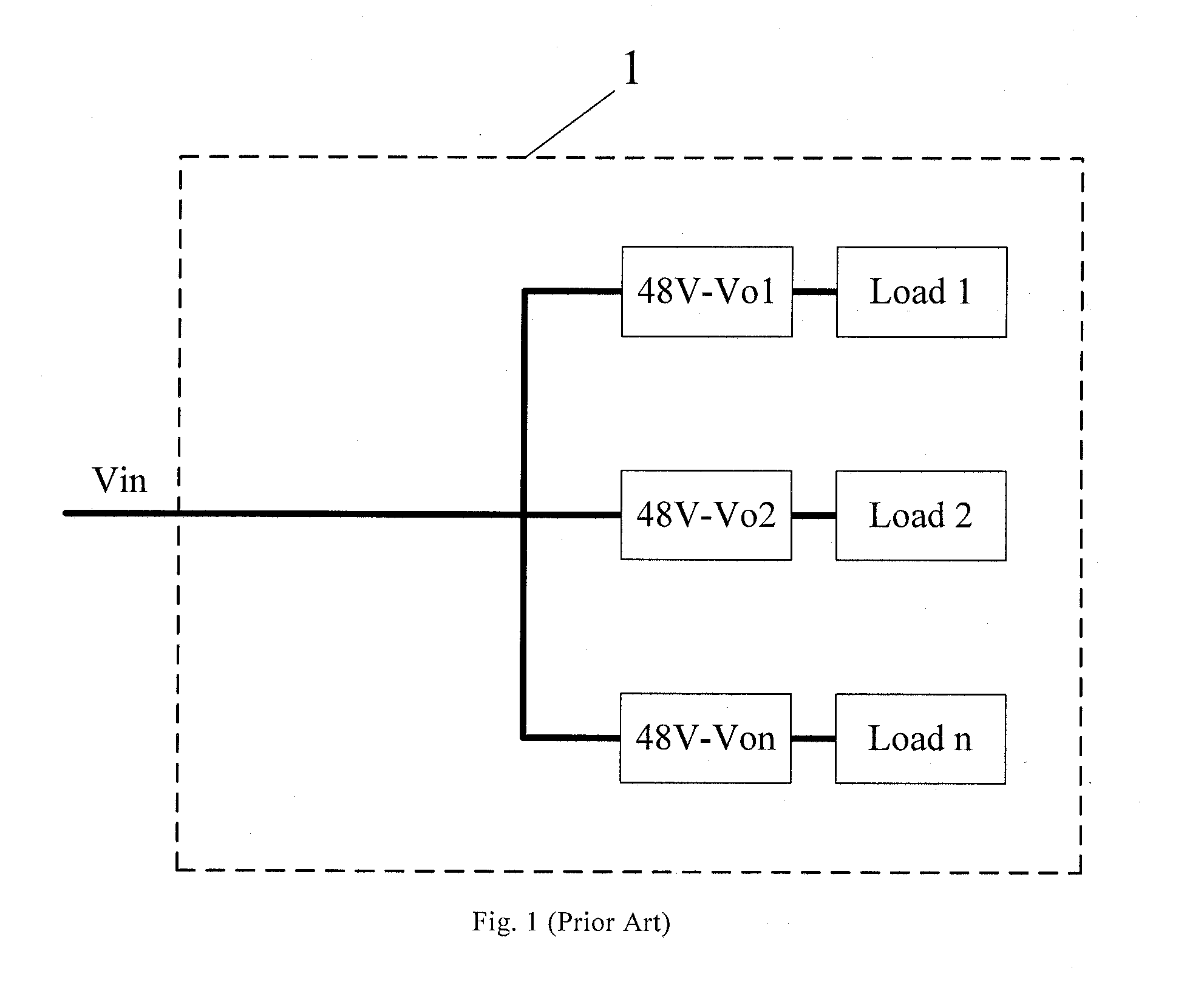
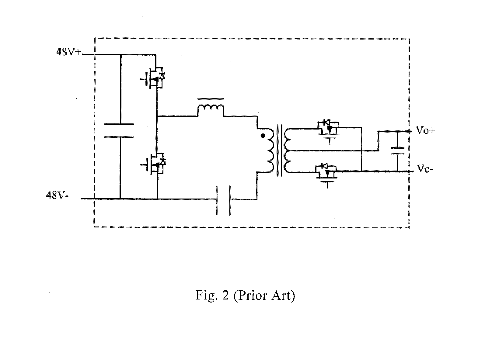
If the input voltage of the POL is 48V, compared with the traditional input voltage of 12V, the value of the voltage is increased by 4 times. Although the POL having the traditional input voltage of 12V is typically implemented with a BUCK circuit, it is difficult to implement the POL having the input voltage of 48V with a BUCK circuit since the duty cycle is too small.
In addition, the single-stage isolation converter having the input voltage of 48V is of a relatively complex configuration.
Also, the single-stage isolation converter having the input voltage of 48V has a limited power if it directly supplies power to a single load, and thus is not suitable for parallel multiplex to achieve reduced capacitor volume and improved light load efficiency.
Accordingly, it is hardly possible for the single-stage isolation converter having the input voltage of 48V to meet the future demand.

Method used


Image

  • Power converter
  • Power converter
  • Power converter

Examples


first embodiment

A First embodiment

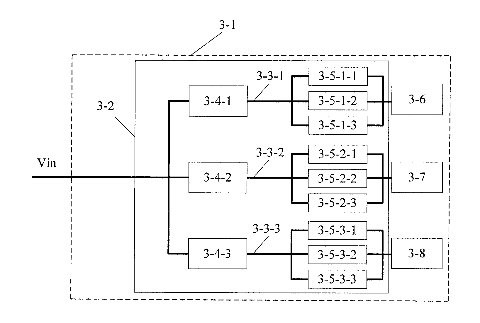
[0034]The present embodiment provides a power converter including a two-stage circuit, which includes a pre-stage circuit and a post-stage circuit. The pre-stage circuit is configured to receive an input voltage, and convert the received input voltage to a bus voltage and output a bus voltage. The post-stage circuit can be a plurality of post-stage circuits connected in parallel to an output terminal of the pre-stage circuit. Each of the post-stage circuits is configured to receive the bus voltage output by the pre-stage circuit, convert the bus voltage to an output voltage and provide it for a load connected to an output terminal of the post-stage circuit.

[0035]Next, the power converter of the present embodiment will be described with reference to specific examples.

[0036]FIG. 3A is a schematic diagram of a power converter provided by an embodiment of the present disclosure. As shown in FIG. 3A, a power converter 3-2 includes a plurality of pre-stage circuits and a...

second embodiment

The Second Embodiment

[0052]FIG. 7 shows a schematic diagram of a package structure of the power converter. As shown in FIG. 7, the pre-stage circuit 7-2 (for example, a LLC circuit) and the plurality of post-stage circuit 7-3 (for example, BUCK circuits) are packaged in an independent module respectively, and are disposed on the data processing board 7-1. A CPU 7-6 and a radiator 7-7 are also disposed on the data processing board 7-1, wherein the radiator 7-7 dissipates heat from the CPU 7-6 and the power converter provides power to the CPU 7-6. The pre-stage circuit 7-2 includes an output capacitor 7-4 and each of the plurality of post-stage circuits 7-3 includes an input capacitor 7-5. The pre-stage and plurality of post-stage circuits are disposed in a respective package module, to form two separate components. In practical application, the distance between the output capacitor 7-4 of the pre-stage circuit and the input capacitors 7-5 of the plurality of post-stage circuit is so ...


PUM


Abstract

The present disclosure provides a power converter, including: a pre-stage circuit, configured to receive an input voltage and convert the input voltage to a bus voltage; and plurality of post-stage circuits, connected in parallel to an output terminal of the pre-stage circuit, and configured to receive the bus voltage from the pre-stage circuit and each converts the bus voltage to an output voltage. The power converter provided by the present disclosure can effectively solve the problems of isolation and the wide range of operating voltage, and can take both of high efficiency and high power density into consideration.

Description

CROSS REFERENCE[0001]This application is based upon and claims priority to Chinese Patent Application No. 201510390600.8, filed on July 6, 2015, the entire contents thereof are incorporated herein by reference.TECHNICAL FIELD[0002]The present disclosure relates to the field of a power module technology, and more particularly, to a power converter.BACKGROUND[0003]With growth of people's demand for an ever intelligent lifestyle, demand for high capacity of data processing is also growing. Energy consumption in data processing has reached about hundreds of billions of or even trillions of kilowatts-hour each year, and a large data center can occupy an area up to tens of thousands of square meters. Accordingly, high efficiency and high power density are significant indicators of a health development of the data center industry.[0004]A critical unit of the data center is a server, which is typically equipped with a mainboard composed of data processing chips (such as a CPU, chipsets, a m...

Claims


Application Information

Patent Timeline
IPC IPC(8): H02J5/00H02M1/14
CPCH02M1/14H02J5/00H02M3/33592Y02B70/10H02M1/0048H02M1/008H02M3/33571
Inventor ZENG, JIANHONGHU, PEIQINGYE, HAOYICHEN, YANDAI, JIALEZHOU, ZIYING
Owner DELTA ELECTRONICS INC
Learn More