Electronic cigarette provided with accumulated e-liquid removal function, and method therefor

a technology of electronic cigarettes and e-liquid, which is applied in the direction of ohmic-resistance heating, tobacco, temperature control using digital means, etc., can solve the problems of reducing user experience, contaminating electronic cigarettes and objects contacted, and blocking the smoke channel, so as to improve user experience

Inactive Publication Date: 2017-01-19
HUIZHOU KIMREE TECH
View PDF33 Cites 54 Cited by
  • Summary
  • Abstract
  • Description
  • Claims
  • Application Information

AI Technical Summary

Benefits of technology

[0061]Implementing the electronic cigarette provided with an accumulated e-liquid removal function and the method for removing accumulated e-liquid of an electronic cigarette in this invention, the following beneficial effects can be achieved: The electronic cigarette is provided with a smoke channel for smoke to flow through. In the present invention, the heating assembly provided in the smoke channel is controlled by the control assembly to produce heat to allow e-liquid accumulated in the smoke channel to be re-atomized, thereby achieving the goal of removal of the accumulated e-liquid and improvement of the user' experience.

Problems solved by technology

The accumulation of non-atomized e-liquid in the smoke channel would not only lead to inhale in e-liquid by smokers, but also result in blockage of the smoke channel and affect the user experience.
More seriously, the more and more accumulated e-liquid in the smoke channel would flow out of the channel, leading to contamination of the electronic cigarette and the objects contacted with.
For this situation, the commonly used simple method is manual clean of the e-liquid, which would reduce the user experience.
Therefore, the prior art needs to be improved due to the defects.

Method used


Image

  • Electronic cigarette provided with accumulated e-liquid removal function, and method therefor
  • Electronic cigarette provided with accumulated e-liquid removal function, and method therefor
  • Electronic cigarette provided with accumulated e-liquid removal function, and method therefor

Examples


first embodiment

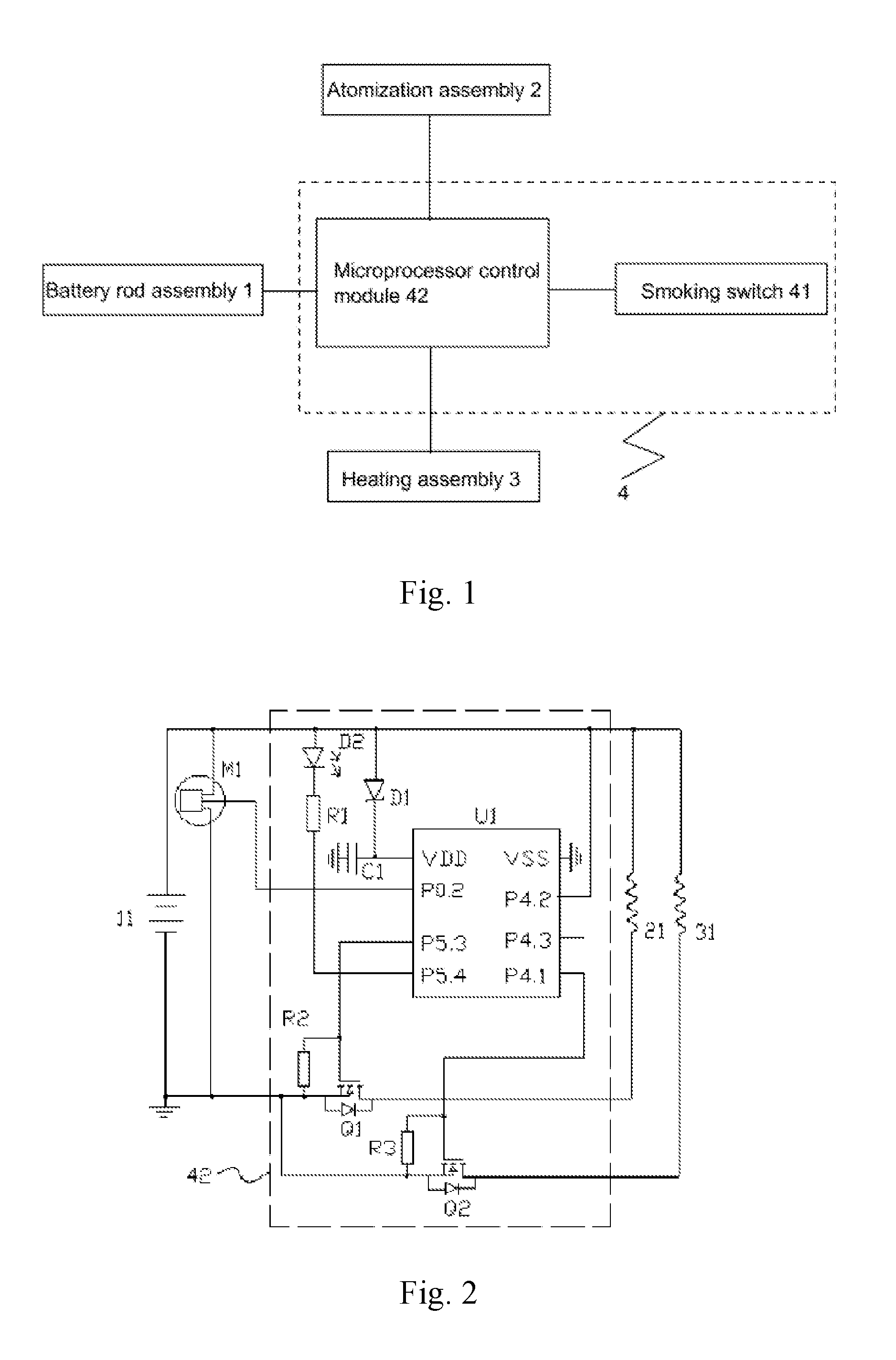
[0087]Specifically, FIG. 2 is a circuit diagram of an electronic cigarette provided with an accumulated e-liquid removal function in the

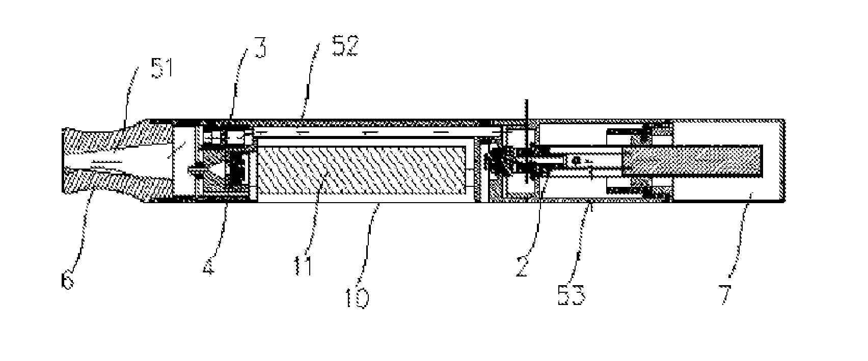
[0088]The smoking switch 41 is an airflow sensor M1, the battery rod assembly 1 comprises a battery 11, the atomization assembly 2 comprises a first electric wire 21, the heating assembly 3 comprises a second electric wire 31.

[0089]The microprocessor control module 42 comprises a SN8P2711B type microcontroller U1, a first MOS transistor Q1 which is N typer and is used for controlling an electric connection between the first electric wire 21 and the battery 11, a second MOS transistor Q2 which is N typer and is used for controlling the electric connection between the second electric wire 31 and the battery 11, a zener diode D1, a capacitance C1 and a light-emitting diode D2 used for smoking indication.

[0090]A VDD pin of the microcontroller U1 is connected to a negative electrode of the zener diode D1, a positive electrode of the zener diode D1 is con...

second embodiment

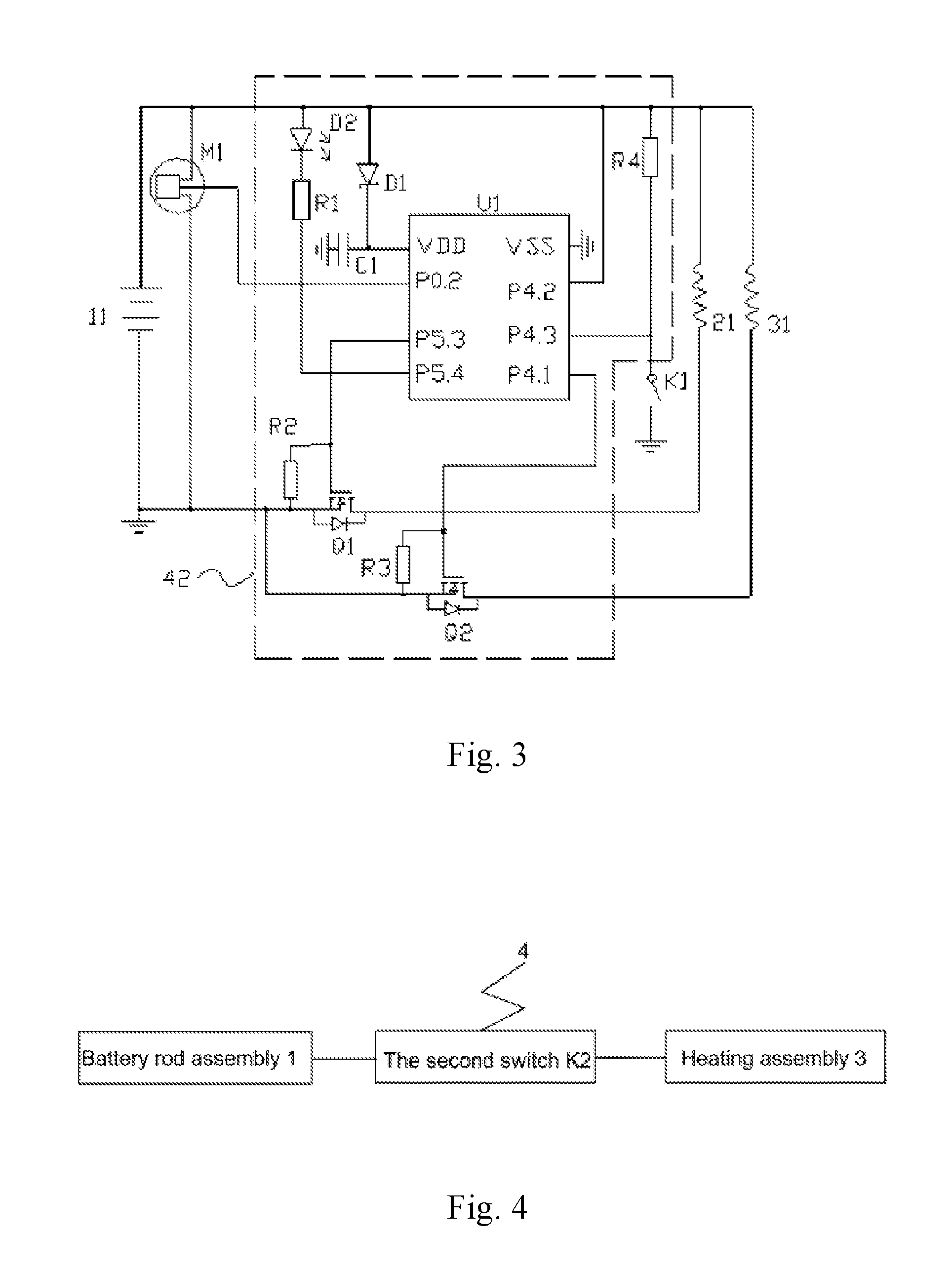
[0096]For reference, FIG. 3 is a circuit diagram of an electronic cigarette provided with an accumulated e-liquid removal function in a

[0097]In the first embodiment, the control assembly 4 is fully automatic, in the second embodiment, the control assembly 4 is automatic or optional manual.

[0098]In the second embodiment, the control assembly 4 also comprises a first switch K1 electrically connected to the microprocessor control module 42. The microprocessor control module 42 also used for controlling the battery rod assembly 1 to supply power to the heating assembly 3 and reset the smoking times when the first switch K1 was triggered. In this embodiment, the first switch K1 is a spring back switch.

[0099]Specifically, differences from the circuit of the first embodiment is that the P4.3 pin of the microcontroller U1 is connected to the negative electrode of the battery 11 through the first switch K1, the P4.3 pin of the microcontroller U1 is also connected to the positive electrode of...

third embodiment

[0102]In the third embodiment, the control assembly 4 belongs to a full manual control. The control assembly 4 is a second switch K2, the second electric wire 31 is connected to the battery 11 through the second switch K2, in this embodiment, the second switch K2 is a press switch. In this condition, the control of the battery rod assembly 1 supplying power for atomization assembly 2 can be realized by controlling the controller or switch, which is existing technology, and is no longer repeated here.

[0103]When it is need to remove the accumulated e-liquid, the user directly presses on the second switch K2, after removing then presses the second switch K2 to stop atomization. Certainly, this embodiment just provides a way to realize a manual control of the removal of e-liquid. In fact, generally electronic cigarettes have a controller, so only need to design a switch which can give a trigger signal to the controller, that is a manual trigger of the controller to realize re-atomizing,...


PUM


Abstract

An electronic cigarette provided with an accumulated e-liquid removal function and a method for removing accumulated e-liquid of an electronic cigarette. The electronic cigarette comprises an atomization assembly for atomizing e-liquid to produce smoke and a battery rod assembly configured for supplying power. The electronic cigarette is provided with a smoke channel for smoke to flow through, a heating assembly provided in the smoke channel and a control assembly for controlling the heating assembly which is configured for re-atomizing non-atomized e-liquid accumulated in the smoke channel. Implementation of the electronic cigarette provided with the accumulated e-liquid removal function and the present method for removing accumulated e-liquid provides the following beneficial effect: the heating assembly provided in the smoke channel is controlled by the control assembly to produce heat to allow e-liquid accumulated in the smoke channel to be re-atomized, thereby achieving the goal of removal of the accumulated e-liquid.

Description

TECHNICAL FIELD[0001]The present application relates to the field of daily electrical products, and more particularly relates to an electronic cigarette provided with accumulated e-liquid removal function, and method therefor.BACKGROUND[0002]An electronic cigarette comprises an atomization assembly and a battery rod assembly. E-liquid in e-liquid reservoir is guided to the atomization assembly. When smoking, the battery rod assembly supplies power to the atomization assembly to produce heat. Therefore, the e-liquid is atomized to produce smoke for user to inhale in.[0003]Some atomized e-liquid can be condensed when flowing in the smoke channel, or e-liquid leaks from the e-liquid reservoir. The accumulation of non-atomized e-liquid in the smoke channel would not only lead to inhale in e-liquid by smokers, but also result in blockage of the smoke channel and affect the user experience. More seriously, the more and more accumulated e-liquid in the smoke channel would flow out of the c...

Claims


Application Information

Patent Timeline
Patent Type & Authority Applications(United States)
IPC IPC(8): A24F47/00G05D23/19H05B1/02A24F40/10A24F40/50
CPCA24F47/008H05B2203/021G05D23/1917H05B1/0244H05B1/0227A24F40/10A24F40/50
Inventor LIU, QIUMING
Owner HUIZHOU KIMREE TECH
Why Eureka
Try Eureka